


Cars up to 9/89 issue and "station wagon" models
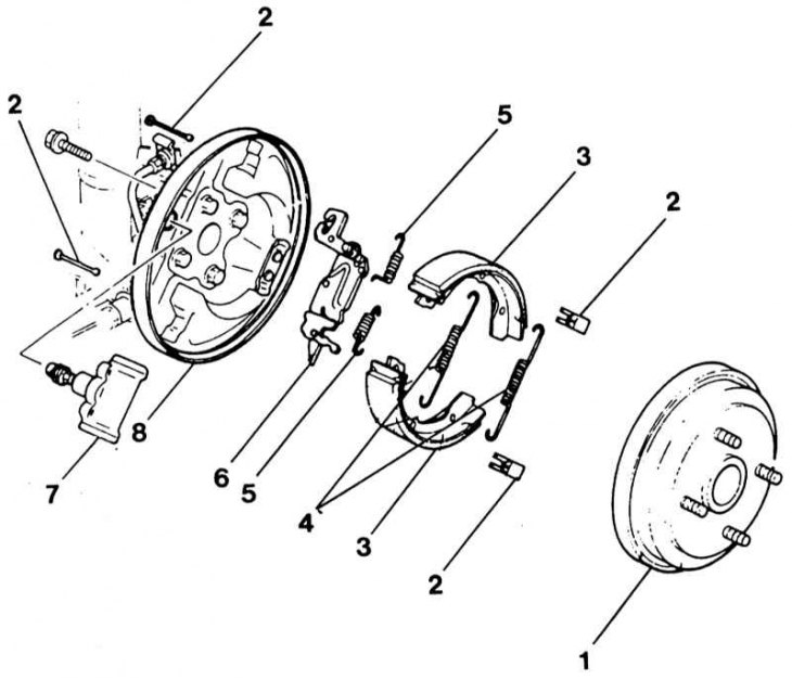
1 - brake drum; 2 - pin and fastening spring; 3 - front and rear brake pads; 4 - return springs; 5 - damping springs; 6 - adjustment device; 7 - wheel brake cylinder; 8 - brake shield
Attention! Remove the parts in the order of their numbering. The individual elements of the right and left brakes are different from each other and must not be mixed up.
Removal
1. Change the position of the wheel disk relative to the hub so that the balanced wheel can be installed in its original position.
2. Loosen the wheel nuts of the vehicle while it is parked on the ground.
3. Raise the rear of the vehicle.
4. Remove the wheel.
5. Release the handbrake.
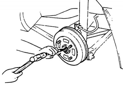
6. Straighten the lock plate with a hammer and chisel and loosen the hub nut.
Attention! On the left side, the hub nut has a left-hand thread, to loosen it you need to turn it to the right (clockwise).
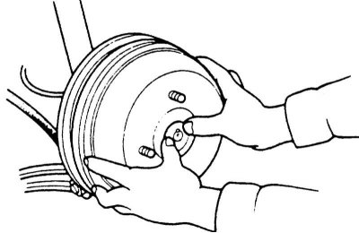
7. Remove the brake drum, making sure that the hub bearing does not fall out. If the brake drum cannot be removed, loosen the handbrake cable completely.
8. Before removing the return springs, it is recommended to mark their installation position. This will make installation easier.
9. Press the pressure spring firmly and turn it 90. While pressing, hold the pin at the back of the brake shield. Remove the pin on the other shoe in the same way.
10. Fold the front shoe outward and disconnect springs "4" and "5".
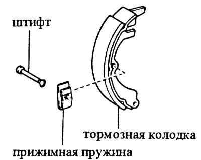
11. Remove both brake pads.
Caution! When the brake pads are removed, do not press the brake pedal, otherwise the piston will jump out of the wheel brake cylinder. For piston installation, see Section Wheel brake cylinder repair.
12. Using a screwdriver, attach the handbrake cable to the adjusting device. Remove the adjusting device.
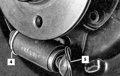
13. Remove boot "5" on the wheel brake cylinder.
Caution! The piston should not be pulled out. Check if there is moisture behind the dust cover. Repair the wheel cylinder if necessary.
14. Place the boot on the wheel cylinder.
Installation
Important! Always replace all 4 brake shoes, even if only one has reached the wear limit. Use shoes of the same brand. Clean the brake drum and brake shield with a vacuum cleaner or alcohol. If the wheel brake cylinder is wet, replace it. Lightly lubricate the adjuster with MoS2 grease. Ream the drums that have grooves, always treating both drums. Brake drums can be reamed to a maximum diameter of 201 mm.
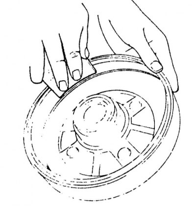
1. Remove minor irregularities and traces of rust with fine sandpaper.
2. Clean the six contact surfaces between the brake pads and the brake shield and coat with a thin layer of heat-resistant grease, preferably high-temperature copper paste, before installing the pads.
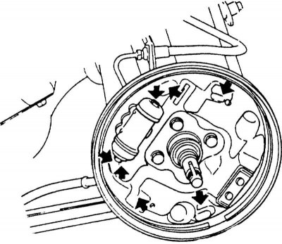
3. Attach the springs to the adjuster and brake shoes.

4. Before installing the brake pads, move the segment of the adjuster until it is adjacent to the brake shield. This sets the distance of the pads to the smallest value. To move the segment, insert a screwdriver between the pin and the segment and turn it in the direction of the arrow. View of the brake from above.
5. Insert the brake shoes first at the bottom, opposite the wheel cylinder. Install the adjuster on top between the shoes and simultaneously install the shoes on both sides of the wheel cylinder.
Caution! Do not load the wheel cylinder on one side only, otherwise the piston will be pushed out on the other side.
6. Attach the handbrake cable to the lever.

7. Install the rear and front brake shoes on the brake shield and secure them with the mounting pin and pressure spring. While holding the pin at the back, simultaneously press the spring with pliers and turn it 90°.
8. Check the operation of the automatic adjustment device. To do this, press the brake pedal 2-3 times (assistant). The adjustment segment should move. If this does not happen, the brake pads were installed incorrectly.
9. Set the adjustment device to the shortest adjustable length.
10. Install the brake drum and screw it on new nut hubs.
11. Adjust the hub bearing play.
Caution! Lock the nut after adjustment, see Chapter Suspension and steering system.
12. Screw the wheel on, observing the mark on the hub. Lower the car and tighten the wheel nuts crosswise with force 100 Nm.
13. Adjust the main clearance of the rear brakes by pressing the brake pedal several times. Clicking sounds can be heard in the brake.
14. Adjust the handbrake.
15. Perform a test braking at medium speed on a road free of traffic.
Cars from 10/89 issue, except for the "station wagon" model
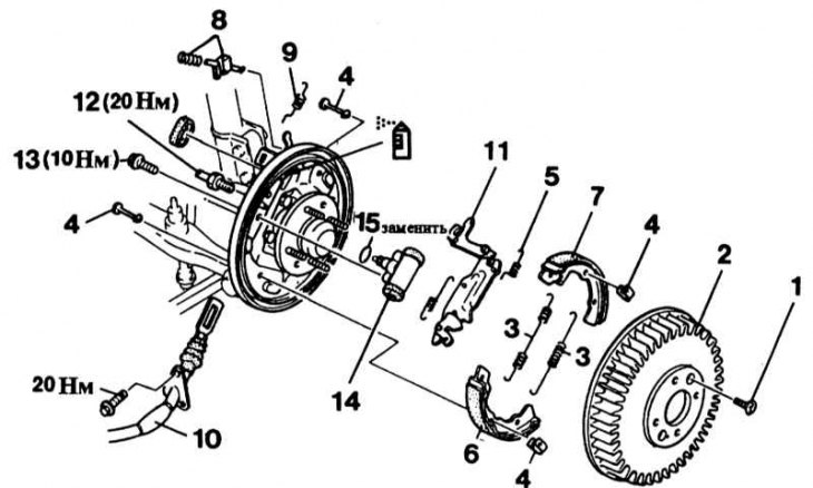
1 - mounting bolt; 2 - brake drum; 3 - return spring; 4 - mounting pin and spring; 5 - anti-squeak spring; 6 - brake shoe; 7 - brake shoe; 8 - thrust spring and bracket; 9 - return spring; 10 - handbrake cable; 11 - drive lever; 12 - brake line; 13 - Wheel brake cylinder bolt; 14 - wheel brake cylinder; 15 - gasket
 lubricate (high temperature paste)
Caution! Remove parts in numerical order. Individual components of the right and left brakes differ from each other; they cannot replace each other.
Removal
1. Mark the position of the wheel disc relative to the hub so that the balanced wheel can be installed in its original position.
2. Loosen the wheel nuts of the vehicle while it is parked on the ground.
3. Raise the rear of the vehicle.
4. Remove the wheel.
5. Unscrew bolt "1" on the brake drum.
6. Release the handbrake and remove the brake drum from the hub. If the brake drum cannot be removed due to running-in, first completely loosen the cable on the handbrake lever.
7. Before removing the return springs, it is recommended to mark their installation position. This will make their installation easier.
8. Disconnect the upper and lower return springs using a screwdriver or special pliers.
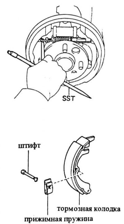
9. Press the pressure spring firmly and turn it 90°. While pressing, simultaneously hold the pin behind the brake shield. Remove the pin on the other brake shoe in the same way.
10. Disconnect the return spring from the adjustment device.
11. Tilt the brake pads outward and remove them.
Caution! When the brake pads are removed, do not press the brake pedal, otherwise the pistons will jump out of the wheel brake cylinder. Insert the pistons, see Section Wheel brake cylinder repair.
12. Disconnect the handbrake cable from the adjuster "11" using a screwdriver. Remove the adjuster.
13. Remove boot "5" on the wheel brake cylinder.
Attention! The piston should not be pulled out. Check for moisture behind the dust cover. Replace the wheel cylinder if necessary.
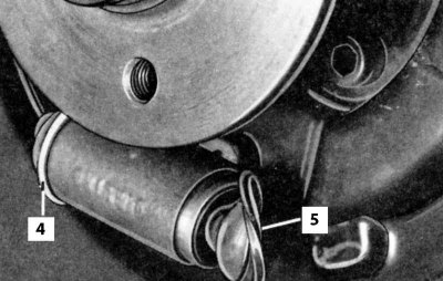
14. Install the boot on the wheel cylinder.
Installation
Important! Always replace all 4 brake shoes, even if only one has reached the wear limit. Use shoes of the same brand. Clean the brake drum and brake shield with a vacuum cleaner or alcohol. If the wheel brake cylinder is wet, replace it. Lightly lubricate the adjuster with MoS2 grease. Ream the drums that have grooves, always treating both drums. Brake drums can be reamed to a maximum diameter of 201 mm.
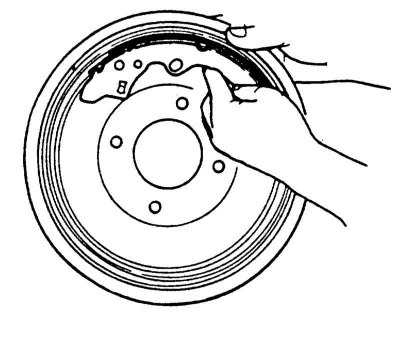
1. Remove minor unevenness and traces of rust with fine sandpaper. If the brake drum has been bored or replaced, insert the brake shoes before installation and check that they have uniform contact with the drum.
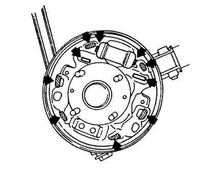
2. Clean the contact surfaces between the brake pads and the brake shield, as well as the wheel cylinder, and before installing the pads, coat with a thin layer of heat-resistant grease, preferably high-temperature copper paste. Also lubricate the contact points of the adjustment device.
Caution! Do not allow grease to come into contact with the brake pads and linings.
3. Attach the springs to the adjuster and brake shoes.
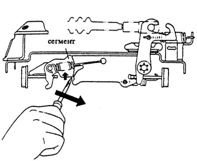
4. Before installing the brake pads, move the segment of the adjuster until it is adjacent to the brake shield. This sets the distance of the pads to the smallest value. To move the segment, insert a screwdriver between the pin and the segment and turn it in the direction of the arrow. View of the brake from above.
5. Insert the brake shoes first at the bottom, opposite the wheel cylinder. Install the adjuster on top between the shoes and simultaneously install the shoes on both sides of the wheel cylinder.
Caution! Do not load the wheel cylinder on one side only, otherwise the piston will be pushed out on the other side.
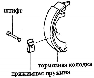
6. Install the rear and front brake shoes on the brake shield and secure them with the mounting pin and pressure spring. While holding the pin at the back, simultaneously press the spring with pliers and turn it 90°.
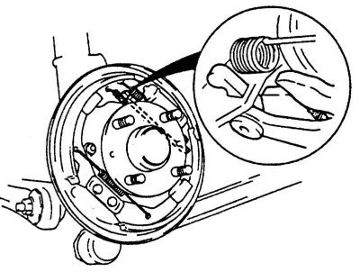
7. Insert the upper and lower return springs into the brake shoes using special pliers.
Attention! Ensure that the return springs are positioned correctly.
8. Attach the handbrake cable to the lever.
9. Check the operation of the automatic adjustment device. To do this, press the brake pedal 2-3 times (with the help of an assistant). The adjustment segment should move. If this does not happen, the brake pads were installed incorrectly.
10. Set the adjustment device to the shortest adjustable length.
11. Install the brake drum and screw on the new hub nut.
12. Screw the wheel on, observing the mark on the hub. Lower the car and tighten the wheel nuts crosswise with force 100 Nm.
13. Adjust the main clearance of the rear brakes by pressing the brake pedal several times. Clicking sounds can be heard in the brake.
14. Adjust the handbrake.
15. Perform a test braking at medium speed on a road free of traffic.