


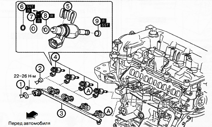
1. Fuel pressure sensor connector.
2. Fuel injector connectors.
3. Fuel rail.
4. Fuel injectors.
5. Spacer.
6. Retaining ring.
7. O-ring with circular cross-section.
8. Lock washer.
9. Teflon seal.
Note.
: replace the part with a new one after each removal.
: use a special tool or device.
: apply oil.
Attention.
- Leaks in fuel lines in a pressurized system are dangerous. Fuel can ignite and cause equipment damage, serious injury, or even death. Fuel can also come into contact with human skin and eyes. To prevent this, it is essential to perform a pressure relief procedure in the fuel system.
- A person carrying a static charge can cause a fire or explosion, which could result in death or serious injury. Before working on the fuel system, you must discharge static electricity by touching the vehicle body.
- Touching the tip of the fuel injector with your hand or pressing it with any object may cause a malfunction. Use extreme caution when handling fuel injectors.
- When removing the fuel rail, the sealing of the fuel injectors is broken. Be sure to replace the retaining rings, O-rings and Teflon seals of the fuel injectors with new ones.
- Do not remove the pressure sensor from the fuel rail.
Removal fuel injectors
1. Perform a pressure release in the fuel system (see the relevant section above).
2. Disconnect the negative battery terminal.
3. Remove the decorative engine cover.
4. Remove the intake manifold (see chapter "Intake and exhaust system").
5. Disconnect the fuel pressure sensor connector.
6. Disconnect the fuel injector connectors.
7. Remove the high pressure fuel lines.
8. Remove the fuel rail.
9. Remove the fuel injectors.
10. Remove the spacers from the fuel injectors.
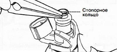
Note: When removing the retaining ring from the fuel injector, be careful not to damage the injector with the tool.
11. Remove the retaining ring from the injector as shown in the figure.
12. Remove the O-ring from the fuel injector.
13. Remove the lock washer from the fuel injector.
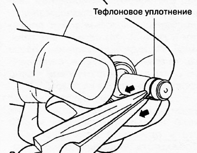
Note: When stretching the Teflon seal, be careful not to damage the nozzle with the tool.
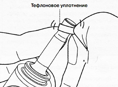
14. Remove the Teflon seal from the fuel injector:
Stretch the Teflon seal as shown in the picture.
Remove the Teflon seal as shown in the figure.
Installing fuel injectors
Installation is performed in the reverse order of removal. After installation, perform the necessary operations after servicing the power supply system.
When installing, consider the following:
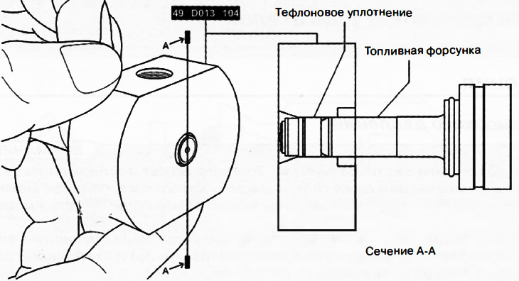
Installing a Teflon Seal on a Fuel Injector
Note: Tools 49 D013 102, 49 D013 103 and 49 D013 104 are components of kit 49 0013 1A0.
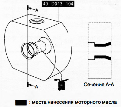
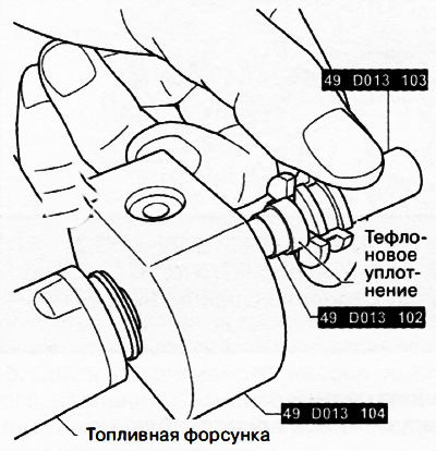
Apply engine oil to tool 49 0013104.
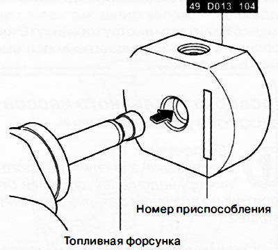
Install tool 49 0013 104 with the mark towards the fuel injector.
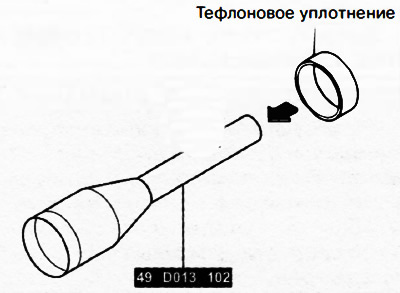
Insert new Teflon seal onto tool 49 0013 102.
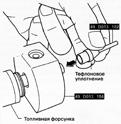
Install tool 49 0013 102 with Teflon ring onto the tip of the fuel injector.
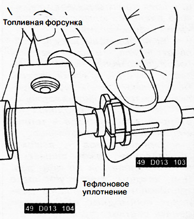
Using tool 49 0013 103, move the Teflon seal towards the fuel injector.
[The article is copied from the website: MAZBOOK]
Move the Teflon seal to the position shown in the figure, then remove tool 49 0013 103.
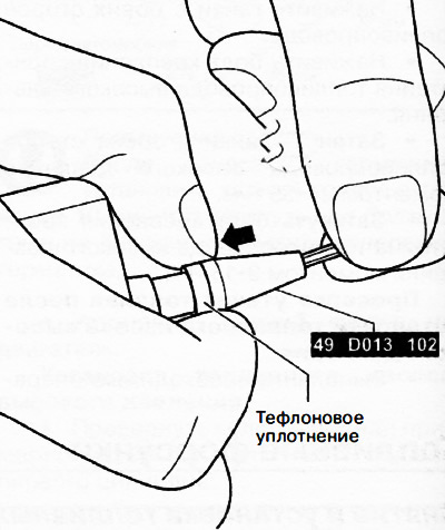
Manually slide the Teflon seal onto the fuel injector and remove tool 49 0013 102.
Move tool 49 0013 104 to the edge of the fuel injector.
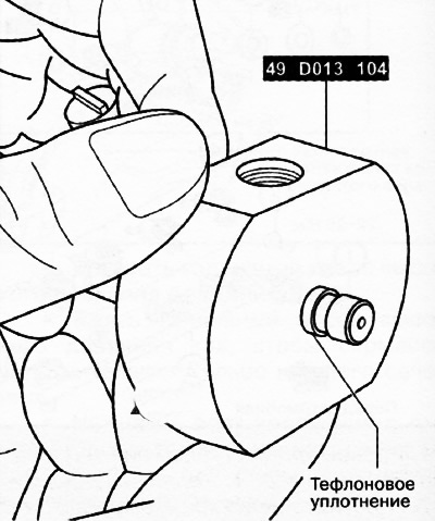
Hold tool 49 0013 104 for at least 30 seconds in the position shown in the figure to correctly position the Teflon seal on the fuel injector.
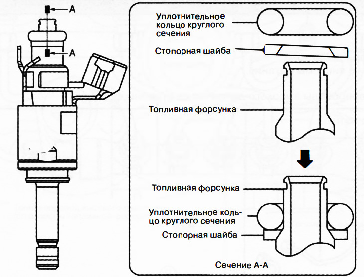
Installing a lock washer on a fuel injector
Install the lock washer in the correct direction.
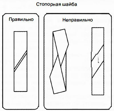
After installing the lock washer, make sure it is installed correctly.
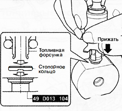
Installing the retaining ring on the retaining nozzle
Note.
- Do not insert the retaining ring at an angle.
- Apply force parallel to the special device.
Place the new retaining ring on the special tool as shown in the figure, making sure the retaining ring is in the correct direction, then press the tool onto the fuel injector until it clicks into place.
Installing fuel injectors
Caution: When applying engine oil to the fuel injector, it may enter the injection holes and impair the quality of fuel atomization. To prevent this, apply engine oil to the cylinder head side.
Apply engine oil to the fuel injector mounting hole threads.
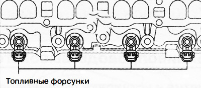
Insert the fuel injectors into the mounting holes one by one, paying attention to the installation direction of the injectors.
Installing the fuel rail
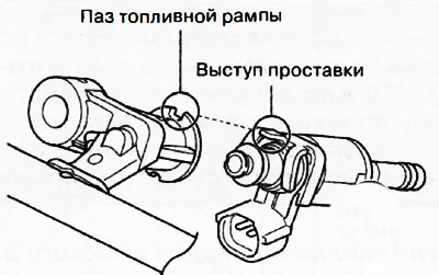
Install the fuel rail onto the fuel injectors, aligning the spacer protrusion with the fuel rail groove.
Tighten the fuel rail mounting bolts until they contact the fuel rail.
Tighten the fuel rail mounting bolts by half a turn in the sequence shown in the figure.
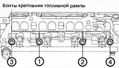
Tighten the fuel rail mounting bolts another half turn in the sequence shown in the figure (just one turn taking into account the previous step).
Tighten the fuel rail mounting bolts in the sequence shown in the figure to a torque of 22-26 Nm.