
Attention.
- Leaks in the fuel lines of a pressurized system are dangerous. Fuel can ignite and cause equipment damage, serious injury or even death. In addition, fuel can get on the skin and in the eyes of a person. To prevent this, it is imperative to perform a pressure relief procedure in the power system.
- A person carrying static electricity can cause a fire or explosion that could result in death or serious injury. Before working on the fuel system, you must remove the static charge from yourself by touching the car body.
- Disconnecting/connecting quick connectors without first cleaning them from the outside can cause damage to the fuel lines and quick connectors. Be sure to clean the quick connector area before disconnecting/connecting with a cloth or soft brush. Make sure there is no foreign material near the quick connector.
1. Place the car on a level surface.
2. Perform Power System Pressure Relief Procedure (see relevant section above).
3. Drain fuel.
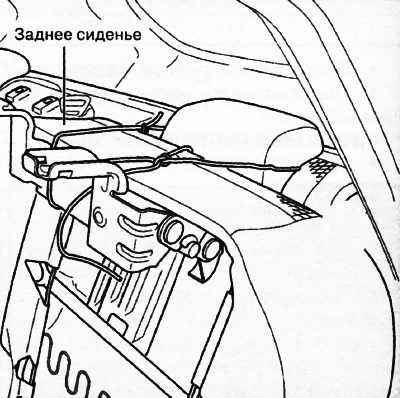
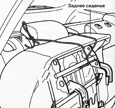
4. Versions with a 6:4 split rear seat backrest: remove the rear seat cushion.
Versions with a 4:2:4 split rear seat: move the rear seat to the side as shown in the illustration.
Main part
Additional part (4WD versions only)
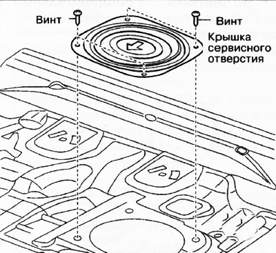
5. Partially unscrew the floor covering as shown in the figure.
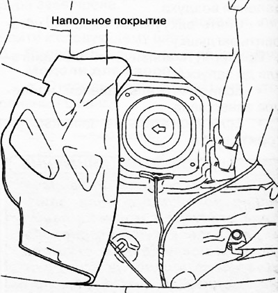
Main part
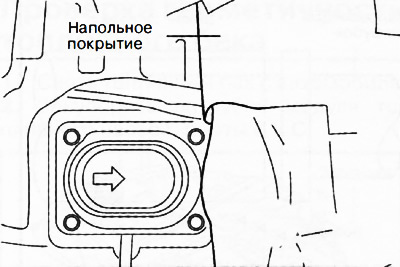
Additional part (4WD versions only)
6. Remove the service port cover.
Main part
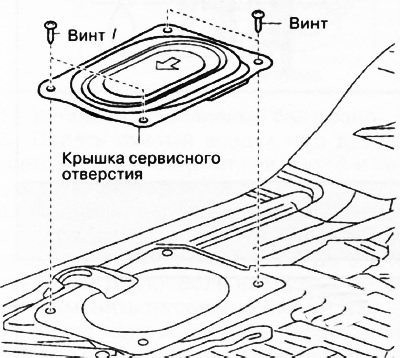
Additional part (4WD versions only)
7. Disconnect the fuel pump connector and quick connector.
8. Versions with all-wheel drive (4WD): Disconnect the connector for the fuel gauge through the service hole of the additional part.
9. Remove the support roof from the underbody.
10. Disconnect the heated oxygen sensor connector.
11. Remove the heated oxygen sensor three-way catalytic converter in one assembly.
12. Versions with all-wheel drive (4WD): Remove propshaft.
13. To remove collars and to remove a connecting hose of a refueling branch pipe.
Note. The pictures below show the fuel tanks of the petrol versions. Versions with diesel engines do not have a carbon filter and an insulator.
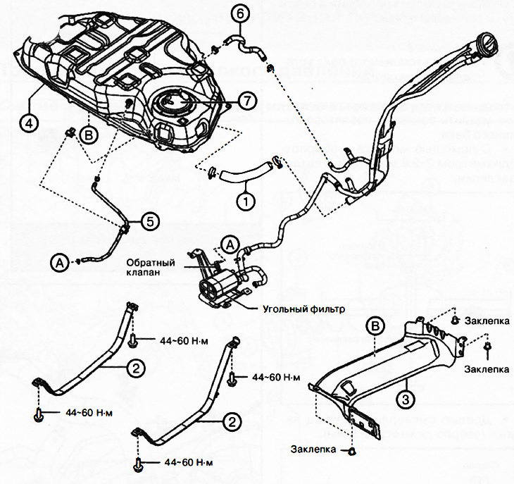
Front wheel drive versions (2WD):
1. Connecting hose
2. Fuel tank clamps.
3. Fuel tank insulator.
4. Fuel tank.
5. Evaporative emission hose.
6. Breather hose.
7. Fuel pump module.
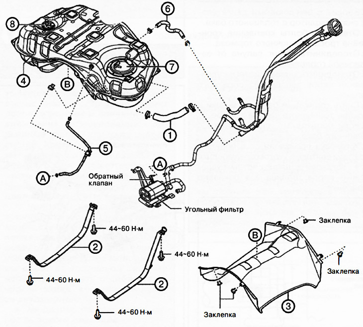
Versions with all-wheel drive (4WD):
1. Connecting hose.
2. Fuel tank clamps.
3. Fuel tank insulator.
4. Fuel tank.
5. Evaporative emission hose.
6. Breather hose.
7. Fuel pump module.
8. Additional fuel gauge module.
14. To turn away bolts of fastening and to remove collars of a fuel tank.
Note. The fuel tank insulator is riveted.
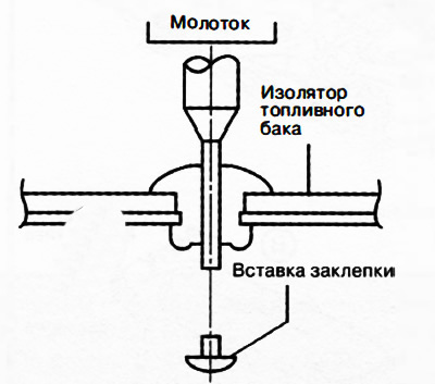
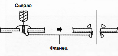
15. Versions with petrol engines: remove fuel tank insulator rivets:
With a hammer and punch (diameter 2-2.8 mm) knock out the rivet insert.
Drill out the flange of the rivet (drill with a diameter of 5 mm).
16. Versions with petrol engines: remove the insulator from the fuel tank.
17. To turn away bolts of fastening of an arm of a cable of a parking brake.
18. Disconnect the breather hose from the filler neck.
19. Disconnect the EVAP hose from the check valve.
20. Remove fuel tank with hoses and fuel pump module assembly.
21. If necessary, remove the hoses from the fuel tank.
22. Installation is carried out in the reverse order of removal, taking into account the following:
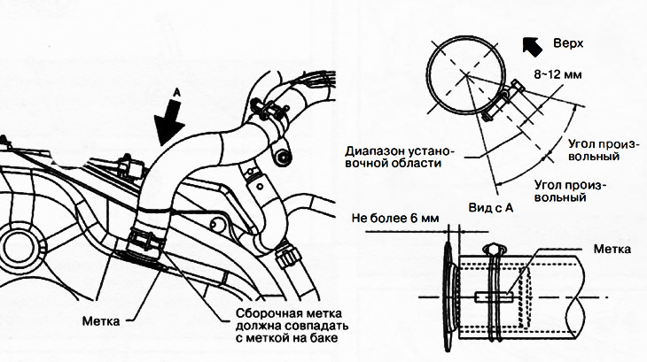
Install the evaporative emission system hose as shown.
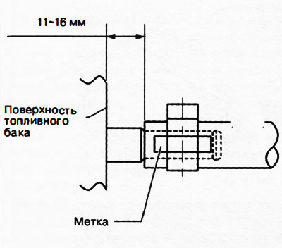
Install the breather hose as shown in the following illustrations.
From the side of the fuel tank
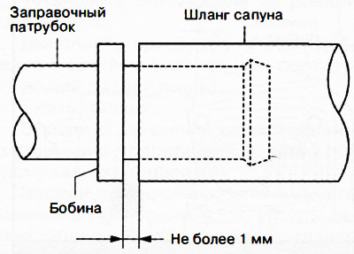
From the side of the filling pipe
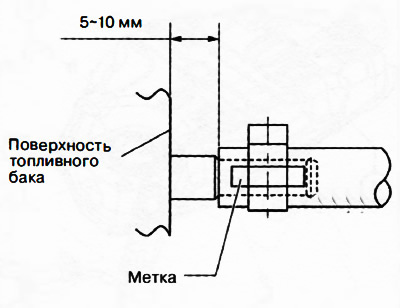
Install the filler connection hose as shown in the following illustrations.
From the side of the fuel tank
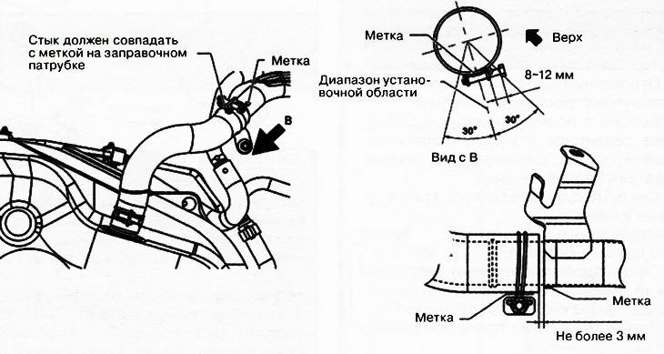
From the side of the filling pipe
23. Perform the necessary operations after servicing the power system.