


Versions with petrol engines
Attention.
- Leaks in the fuel lines of a pressurized system are dangerous. Fuel can ignite and cause equipment damage, serious injury or even death. In addition, fuel can get on the skin and in the eyes of a person. To prevent this, it is imperative to perform a pressure relief procedure in the power system.
- A person carrying static electricity can cause a fire or explosion that could result in death or serious injury. Before working on the fuel system, you must remove the static charge from yourself by touching the car body.
Checking the tightness of the fuel lines
Using the diagnostic tool M-MDS
1. Connect the M-MDS device to the DLC-2 diagnostic socket.
2. Turn on the ignition (do not start the engine).
3. Using the simulation function "FP", turn on the fuel pump.
4. Check for fuel leaks from pressurized fuel system components.
Note. Normally there should be no fuel leaks for five minutes after starting (as a rule, if leaks have not occurred during this time, they will no longer be).
5. If fuel leaks are found, replace the relevant components and repeat the test procedure again.
Note.
- If there are leaks, replace the fuel hoses with clamps.
- If the seals on the side of the fuel lines are damaged, replace the fuel line with a new one.
Without using the M-MDS diagnostic tool
1. Disconnect the negative battery terminal.
2. Remove the fuel pump relay.
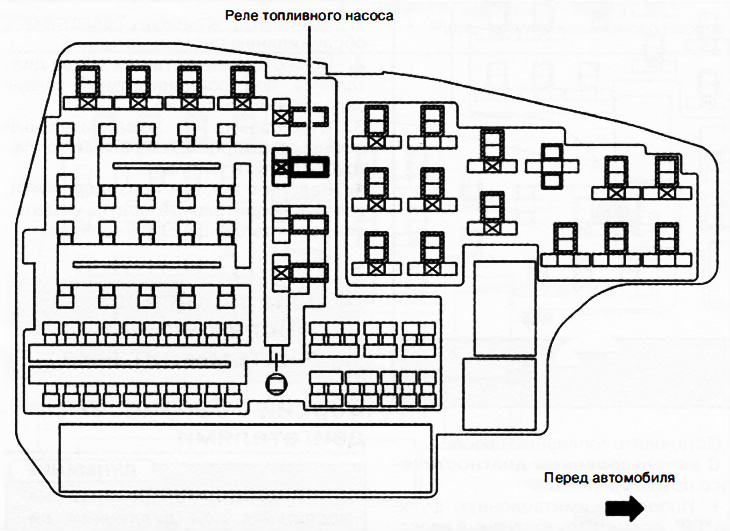
Relay and fuse box
Attention. It is necessary to short the correct terminals, since shorting the wrong terminals of the relay and fuse box may cause malfunctions.
3. Using a jumper, short-circuit terminals C and D of the fuel pump relay in the relay and fuse box.
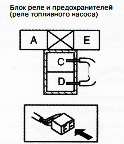
4. Connect the negative battery terminal and start the fuel pump.
5. Check for fuel leaks from pressurized fuel system components.
Note. Normally there should be no fuel leaks for five minutes after starting (as a rule, if leaks have not occurred during this time, they will no longer be).
6. If fuel leaks are found, replace the relevant components and repeat the test procedure again.
Note.
- If there are leaks, replace the fuel hoses with clamps.
- If the seals on the side of the fuel lines are damaged, replace the fuel line with a new one.
Versions with diesel engines
Attention.
- Leaks in the fuel lines of a pressurized system are dangerous. Fuel can ignite and cause equipment damage, serious injury or even death. In addition, fuel can get on the skin and in the eyes of a person. To prevent this, it is imperative to perform a pressure relief procedure in the power system.
- A person carrying static electricity can cause a fire or explosion that could result in death or serious injury. Before working on the fuel system, you must remove the static charge from yourself by touching the car body.
Removal of air from fuel lines
1. Make sure all fuel hoses are securely connected.
Attention. Continued cranking the engine with the starter may drain the battery and damage the starter. To prevent this, it is necessary to ensure that the duration of rotation of the engine crankshaft by the starter does not exceed 10 seconds.
2. Turn the engine crankshaft before starting.
- If the engine starts, the procedure is complete.
- If the engine does not start, go to the next step.
3. Wait 20 seconds.
Attention. Continued cranking the engine with the starter may drain the battery and damage the starter. To prevent this, it is necessary to ensure that the duration of rotation of the engine crankshaft by the starter does not exceed 10 seconds.
4. Turn the engine crankshaft before starting.
- If the engine starts, the procedure is complete.
- If the engine does not start, go to the next step.
5. Perform the following procedure:
Models for Europe
Disconnect the fuel return hose.
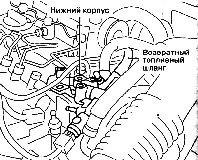
Connect hand pump.
Pump the hand pump several times.
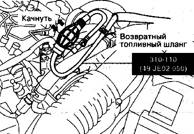
Disconnect hand pump.
Connect the fuel return hose.
Except European models
Remove plug.
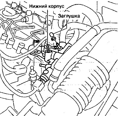
Install the vacuum pump as shown in the illustration.
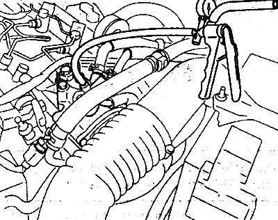
Pump out fuel until air is completely removed.
Remove the vacuum pump and install the plug.
6. Turn the engine crankshaft before starting.
- If the engine starts, the procedure is complete.
- If the engine does not start, repeat step 5.
Attention. Continued cranking the engine with the starter may drain the battery and damage the starter. To prevent this, it is necessary to ensure that the duration of rotation of the engine crankshaft by the starter does not exceed 10 seconds.