
Versions with petrol engines
Checking the pressure in the power system
Attention.
- Fuel vapors are hazardous. They are highly flammable, causing serious injury and damage. Keep fuel away from sparks and open flames.
- Leaks in the fuel lines of a pressurized system are dangerous. Fuel can ignite and cause equipment damage, serious injury or even death. In addition, fuel can get on the skin and in the eyes of a person. To prevent this, it is imperative to perform a pressure relief procedure in the power system.
- A person carrying static electricity can cause a fire or explosion that could result in death or serious injury. Before working on the fuel system, you must remove the static charge from yourself by touching the car body.
- Disconnecting/connecting quick connectors without first cleaning them from the outside can cause damage to the fuel lines and quick connectors. Be sure to clean the quick connector area before disconnecting/connecting with a cloth or soft brush. Make sure there is no foreign material near the quick connector.
1. Perform Power System Pressure Relief Procedure (see relevant section above).
2. Disconnect the negative battery terminal.
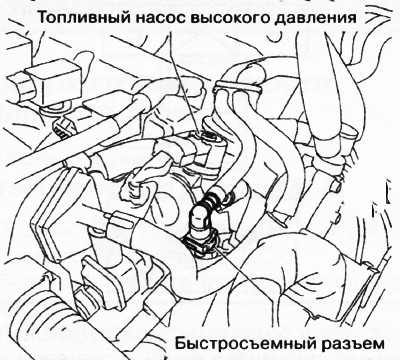
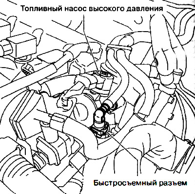
3. Disconnect the quick connector as shown.
4. Turn the fuel gauge lever parallel to the hose as shown.
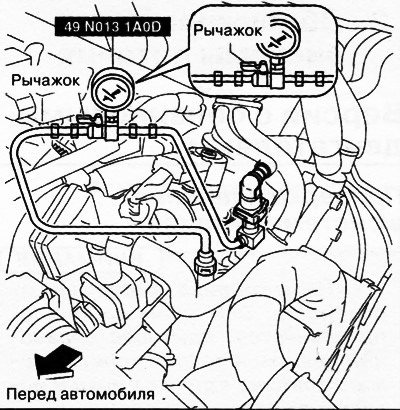
5. Insert the fuel gauge quick connector into the fuel line until it clicks into place.
6. Verify that the quick connector is securely connected by pulling on it with your hand.
7. Start the fuel pump:
Using the diagnostic tool M-MDS
- Connect the negative battery terminal.
- Connect the M-MDS device to the DLC-2 diagnostic socket.
- Using the simulation function "FP", turn on the fuel pump.
Without using the M-MDS diagnostic tool
- Remove the fuel pump relay.
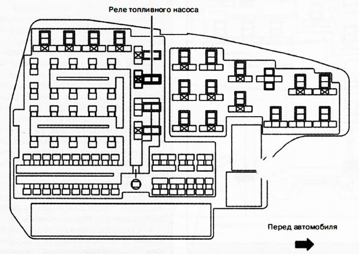
Relay and fuse box
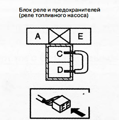
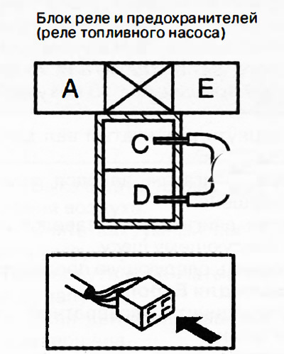
Attention. It is necessary to short the correct terminals, since shorting the wrong terminals of the relay and fuse box may cause malfunctions.
Use a jumper wire to short terminals C and D of the fuel pump relay in the relay and fuse box.
Connect the negative battery terminal and start the fuel pump.
8. Run the fuel pump for 10 seconds.
9. Measure the pressure in the power system. If the measured value is not correct (405-485 kPa (4.13-4.94 kg/cm2)), check the following:
If the pressure value is less than normal:
- Fuel pump module.
- Fuel lines for pinching or leaks.
If the pressure value is higher than normal:
- Fuel lines for pinching.
10. Stop the fuel pump:
Using the diagnostic tool M-MDS
- Using the simulation function "FP", stop the fuel pump.
Without using the M-MDS diagnostic tool
- Disconnect the negative battery terminal to stop the fuel pump.
11. Measure the residual fuel pressure in the fuel system five minutes after stopping. If the measured value is not correct (230 kPa (2.35 kg/cm2)), check the fuel lines for leaks.
12. Perform Power System Pressure Relief Procedure (see relevant section above).
13. Disconnect the fuel pressure gauge.
14. Connect the fuel line quick connector.
15. Perform operations after servicing the power system (see related section below).
Fuel drain procedure
Attention.
- Fuel vapors are hazardous. They are highly flammable, causing serious injury and damage. Keep fuel away from sparks and open flames.
- Leaks in the fuel lines of a pressurized system are dangerous. Fuel can ignite and cause equipment damage, serious injury or even death. In addition, fuel can get on the skin and in the eyes of a person. To prevent this, it is imperative to perform a pressure relief procedure in the power system.
- A person carrying static electricity can cause a fire or explosion that could result in death or serious injury. Before working on the fuel system, you must remove the static charge from yourself by touching the car body.
- Disconnecting/connecting quick connectors without first cleaning them from the outside can cause damage to the fuel lines and quick connectors. Be sure to clean the quick connector area before disconnecting/connecting with a cloth or soft brush. Make sure there is no foreign material near the quick connector.
1. Perform Power System Pressure Relief Procedure (see relevant section above).
2. Disconnect the negative battery terminal.
3. Disconnect the quick connector as shown.
4. Connect a long hose to the disconnected quick connector and drain the fuel into a suitable container.
5. Drain fuel from tank:
Using the diagnostic tool M-MDS
- Connect the negative battery terminal.
- Connect the M-MDS device to the DLC-2 diagnostic socket.
- Using the simulation function "FP", turn on the fuel pump.
Without using the M-MDS diagnostic tool
- Remove the fuel pump relay.
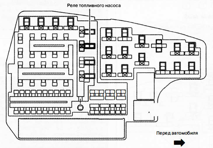
Relay and fuse box
Attention. It is necessary to short the correct terminals, since shorting the wrong terminals of the relay and fuse box may cause malfunctions.
Use a jumper wire to short terminals C and D of the fuel pump relay in the relay and fuse box.
Connect the negative battery terminal and start the fuel pump.
Attention. The fuel pump may be damaged if it runs without fuel in the tank. It is necessary to monitor the amount of fuel flowing through the hose in order to stop the fuel pump in time when the fuel in the tank runs out.
6. Stop the fuel pump:
Using the diagnostic tool M-MDS
- Using the simulation function "FP", stop the fuel pump.
- Disconnect the negative battery terminal.
Without using the M-MDS diagnostic tool
- Remove the jumper to stop the fuel pump.
- Disconnect the negative battery terminal.
Versions with diesel engines
Fuel Hose Installation Procedure
1. When connecting fuel hoses and fuel lines, make sure they are not deformed or damaged.
2. When installing the fuel hose, determine the main and return sides and install it in a certain position.
Fuel drain procedure
Attention.
- Leaks in the fuel lines of a pressurized system are dangerous. Fuel can ignite and cause equipment damage, serious injury or even death. In addition, fuel can get on the skin and in the eyes of a person. To prevent this, it is imperative to perform a pressure relief procedure in the power system.
- A person carrying static electricity can cause a fire or explosion that could result in death or serious injury. Before working on the fuel system, you must remove the static charge from yourself by touching the car body.
1. Complete the power system maintenance preparation procedure.
2. Place a container for collecting diesel fuel under the connecting hose of the filling pipe.
3. Disconnect the connecting hose from the side of the filling pipe and drain the fuel.
4. Versions with all-wheel drive (4WD): Remove the optional fuel gauge module and drain the fuel.