


Removal and installation the high pressure fuel pump
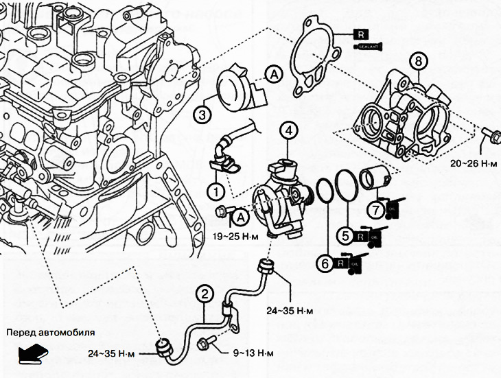
1. Quick release connector.
2. High pressure fuel line.
3. High pressure fuel pump cover.
4. High pressure fuel pump.
5. Rubber seal.
6. O-ring with circular cross-section.
7. Tension sleeve.
8. Rear body.
Note.
: replace the part with a new one after each removal.
: places where sealant is applied.
: apply oil.
Attention.
- Leaks in fuel lines in a pressurized system are dangerous. Fuel can ignite and cause equipment damage, serious injury, or even death. Fuel can also come into contact with human skin and eyes. To prevent this, it is essential to perform a pressure relief procedure in the fuel system.
- A person carrying a static charge can cause a fire or explosion, which could result in death or serious injury. Before working on the fuel system, you must discharge static electricity by touching the vehicle body.
- Do not disassemble the high pressure fuel pump.
- Be careful not to damage the sealing surfaces of the fuel line shut-off valve.
- Damage or deformation of the edge of the high-pressure fuel line may cause fuel leaks.
- Disconnecting/connecting quick-release connectors without first cleaning their outside may cause damage to the fuel lines and quick-release connectors. Be sure to clean the quick-release connector area with a cloth or soft brush before disconnecting/connecting. Make sure there is no foreign material near the quick-release connector.
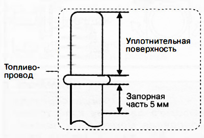
Removal the high pressure fuel pump
1. Perform a pressure release in the fuel system (see the relevant section above).
2. Disconnect the negative battery terminal.
3. Remove the decorative engine cover.
4. Remove the air filter with the air hose as one unit.
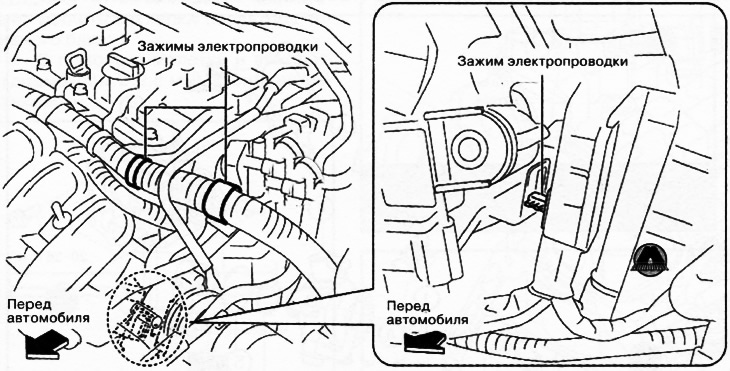
5. Disconnect the wiring clamps shown in the figure.
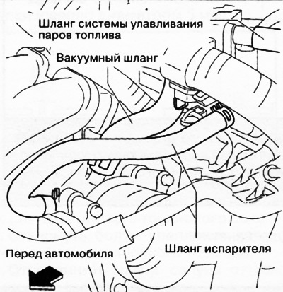
6. Disconnect the hoses shown in the figure.
7. Disconnect the following connectors:
- Electromagnetic purge valve.
- High pressure fuel pump.
- Intake camshaft position sensor.
8. Remove the electromagnetic purge valve with the catcher and bracket as one unit.
9. Disconnect the quick-release connector by prying the retainer with a flat-head screwdriver or similar tool.
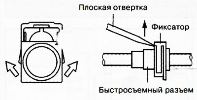
Attention.
- When removing the high-pressure fuel pipe, the edge of the fuel pipe may be damaged due to the small clearance between the high-pressure fuel pump and the fuel pipe. Be extremely careful not to damage the edge of the high-pressure fuel pipe.
- If the high-pressure fuel pump is removed together with the high-pressure fuel line installed, the high-pressure fuel line and the fuel rail may be damaged by the spring action of the high-pressure fuel pump. If damaged, the high-pressure fuel line and the fuel rail must be replaced with new ones. Be sure to remove the high-pressure fuel line before removing the high-pressure fuel pump.
10. Remove the high pressure fuel line.
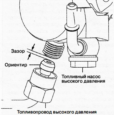
11. Remove the high pressure fuel pump cover.
12. Loosen the mounting bolts and remove the high-pressure fuel pump.
13. Remove the rubber seal, O-ring and tension sleeve from the high-pressure fuel pump.
14. Remove the vacuum pump.
15. Loosen the mounting bolts and remove the rear housing from the engine.
Installing a high pressure fuel pump
Installation is carried out in the reverse order of removal, taking into account the following:
Installing the rear housing
Apply silicone sealant to the areas of the engine shown in the figure.
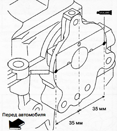
Note: After applying the sealant, install the rear housing within 10 minutes and tighten all bolts within 5 minutes of applying the sealant.
Install the rear housing onto the engine.
Installing a high pressure fuel pump
Turn the crankshaft approximately 90° from the TDC mark of the piston of the first cylinder.
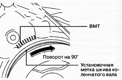
Insert the high pressure fuel pump into the rear housing.
Press the high pressure fuel pump until the O-ring is hidden.
Tighten the mounting bolt on one side of the high-pressure fuel pump so that its head touches the pump body.
Screw in and tighten the second high-pressure fuel pump mounting bolt to a torque of 19-25 Nm.
Tighten the first high-pressure fuel pump mounting bolt to 19-25 Nm.
Installing a high pressure fuel line
Attention.
- Damage or deformation of the edge of the high-pressure fuel line may cause fuel leaks.
- If fuel gets on engine parts, it may cause damage to those components or cause a fire. Be sure to wipe up any spilled fuel with a clean rag.
- Prevent foreign material from entering the high-pressure fuel line.
- The high-pressure fuel line can be removed and installed up to five times. Each time the high-pressure fuel line is removed/installed, it is necessary to make the appropriate notes in the service book. After the fifth reinstallation of the high-pressure fuel line, it must be replaced with a new one.
Tighten the nuts on both sides of the fuel line.
Tighten the high pressure fuel line bracket mounting bolt.
Tighten the nuts on both sides of the high-pressure fuel line to a torque of 24-35 Nm.
Tighten the high pressure fuel line bracket mounting bolt to a torque of 9-13 Nm.
Checking for fuel leaks after installing a high-pressure fuel pump
Perform the necessary operations after servicing the power supply system.
Make sure the high pressure fuel pump is installed securely.
Check for fuel leaks around the high pressure fuel pump.