
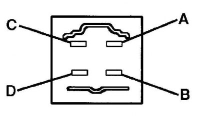
Identification of terminals of the main relay of electronic fuel injection (1990–1994 models)
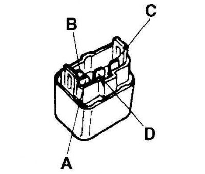
Circuit Open Relay/Fuel Pump Terminal Identification
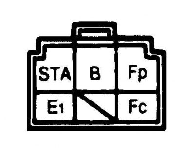
Fuel Pump Relay Terminal Identification (models after 1995 release)
Fuel pump check
1. Connect the F/P or GND terminals of the diagnostic socket with a wire.
2. Remove the fuel filler cap.
3. Turn the ignition key to the ON position.
4. The fuel pump should turn on.
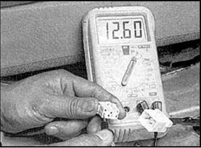
5. If not, check for battery voltage at the fuel pump connector. Measure the voltage between the B/P wire of the pump connector and "weight". It should be 12 volts.
6. If not, check the electronic fuel injection fuse and pump relay.
7. If everything is in order, check for continuity between terminals B/P and B of the pump connector.
8. If there is no continuity, check pump grounding and replace pump if necessary.
Fuel pressure check
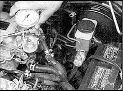
9. Release pressure from the fuel system and connect a pressure gauge with a tee to the fuel supply hose from the fuel filter to the engine. Measure the pressure generated by the fuel pump near the fuel filter.
10. Carry out the operations described in points 1-3 and check the fuel pressure.
11. Start the engine, let it idle and check the fuel pressure again.
12. Stop the engine and check that the fuel pressure does not fall below the minimum allowable. If the pressure drops, there is probably a leak in the pressure regulator, fuel pump, or injectors.
Checking the Fuel Pressure Regulator
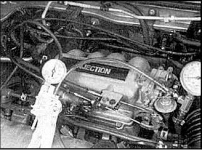
13. Check fuel pressure. Connect the vacuum pump to the pressure regulator and check that the fuel pressure decreases as the vacuum increases.
14. Connect the vacuum hose to the regulator and start the engine. Disconnect the hose and check that the fuel pressure has increased. If the fuel pressure is too high at idle, check for leaks in the air inlet or intake manifold. If not, replace the fuel pressure regulator.
15. If the fuel pressure is low, pinch the return line hose. If the pressure does not increase, then the fuel pump is defective or the fuel supply pipe is clogged.
16. If the fuel pressure is too high, check if the return pipe is blocked. If not, replace the fuel pressure regulator.
Main relay test, circuit opening relay (early models) and fuel pump relay (later models) electronic fuel injection systems
Voltage test
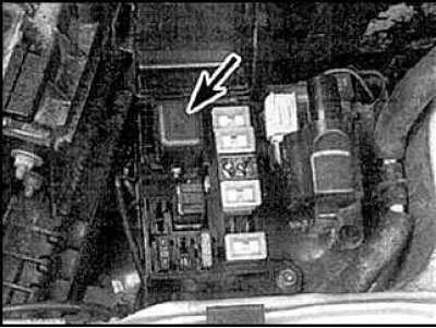 |  |
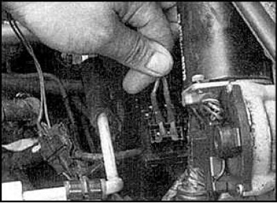
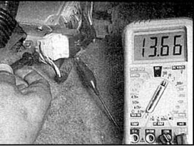
17. Remove the main relay of the electronic fuel injection system (indicated by the arrow in Fig. left) and check that when the ignition is switched on, terminals A and B of the main relay have battery voltage (pic. on right).
18. Check that when the ignition is turned on, the terminals of the light green and white-red wires (early models) or between the terminals of the white-red wires (later models) The fuel pump/open circuit relay had battery voltage.
Main Relay for Electronic Fuel Injection
19. Check that the relay clicks when the ignition is turned on/off.

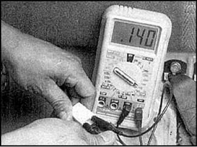
20. Check for continuity between terminals A and B of the relay. When voltage is applied to terminals A and B, conduction should appear between terminals C and D.

21. Check the resistance between the fuel pump/open circuit relay terminals:
- between STA and E1 - 21–43 ohms;
- between B and Fc - 109–226 ohms;
- there must be no continuity between terminals B and Fp.
Fuel pump relay (models after 1995 release)

22. Check for continuity between terminals A and B. When voltage is applied to terminals A and B, continuity should appear between terminals C and D. Replace the relay if necessary.