
1990-1994 Electronic Fuel Injection Schematic Diagram
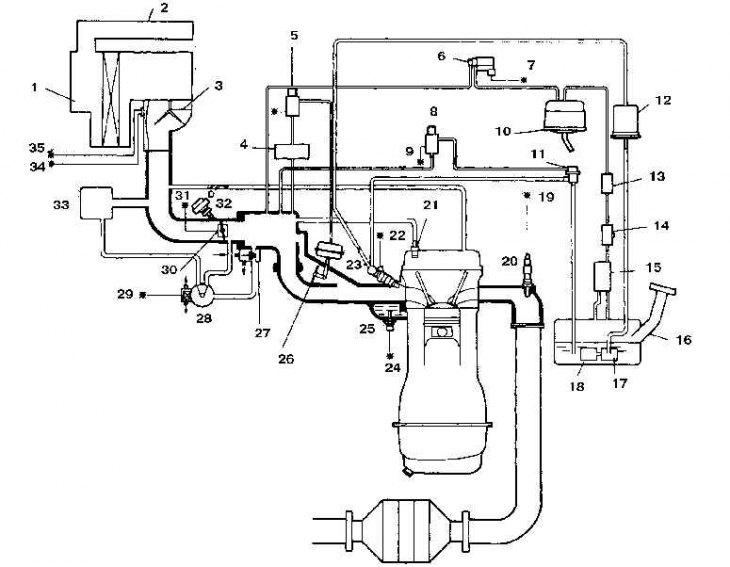
1. Air filter housing; 2. Resonator pipe; 3. Air flow sensor (with temperature sensor); 4. Vacuum chamber *1; 5. Fuel cut-off valve; 6. Carbon filter purge valve; 7. *; 8. Solenoid valve *2 (pressure regulator control valve); 9. *; 10. Charcoal filter; 11. Pressure regulator; 12. Fuel filter; 13. Control valve; 14. Control and shut-off valve; 15. Separator; 16. Fuel tank; 17. Fuel pump; 18. Fuel filter; 19. *; 20. Oxygen sensor; 21. Crankcase ventilation valve; 22. *; 23. Injector; 24. *; 25. Engine coolant temperature sensor; 26. Closing valve; 27. Air valve; 28. Air supply control valve; 29. *; 30. Throttle position sensor; 31.*; 32. Shock absorber; 33. Resonator chamber; 34. *; 35.*
* To the electronic engine control unit
Scheme of the electronic fuel injection system of models after 1995 of release
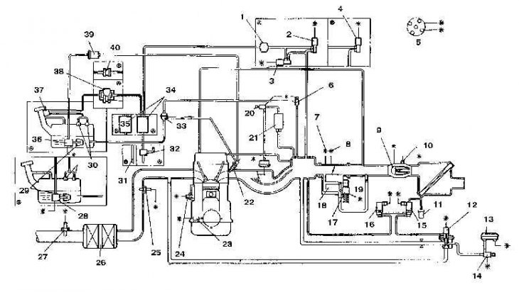
1. Tank for collecting fuel vapors; 2. Purge valve (upper); 3. Purge valve (lower); 4. Purge valve (upper); 5. Camshaft position sensor; 6. Solenoid valve; 7. Throttle position sensor; 8. Throttle closing sensor; 9. Air flow sensor; 10. Inlet air temperature sensor; 11. Air filter; 12. Recirculation valve opening sensor; 13. Recirculation sensor; 14. Solenoid valve; 15. Recirculation valve (ventilation); 16. Recirculation valve (vacuum); 17. Air supply control valve; 18. Solenoid valve; 19. Air valve; 20. Shut-off valve; 21. Vacuum chamber; 22. Injector; 23. Crankshaft position sensor; 24. Coolant temperature sensor; 25. Oxygen sensor (front); 26. Catalytic converter; 27. Oxygen sensor (rear); 28. Fuel pump; 29. Fuel filter; 30. Valve to prevent fuel leakage; 31. Drain hose; 32. Control valve; 33. Pressure regulator; 34. Charcoal filter; 35. Control valve; 36. Fuel pump; 37. Vent valve; 38. Fuel tank pressure control valve; 39. Fuel filter; 40. Control valve
The electronic fuel injection system consists of three subsystems: the power system, the air supply system and the electronic control system.
Supply system
The fuel pump pumps fuel into the fuel manifold, from where it enters the cylinders through the injectors. The amount of fuel injected by the injectors is controlled by an electronic control unit.
Air supply system
The system consists of an air filter, a throttle body, a connecting pipe and an intake air temperature sensor.
Electronic control system
The electronic control system controls the fuel injection system and other systems using an electronic control unit that receives signals from various sensors that monitor intake air temperature, throttle opening angle, coolant temperature, crankshaft speed, vehicle speed and CO content in exhaust gases.
Examination
1. Check wiring connections and grounding.
2. Check battery charge.
3. Check the air filter.
4. Check fuses.
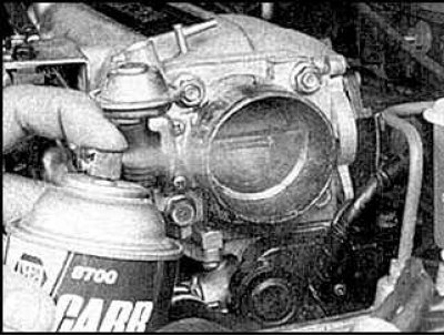
5. Check the air inlet and intake manifold for leaks. Check for clogged air inlet and throttle body. Clean it up if necessary.
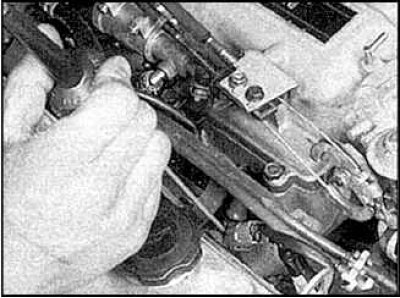
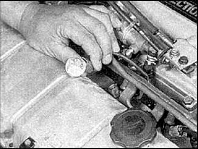
6. Check the injectors by listening to them work with a stethoscope.
7. Check the injectors with a test light.
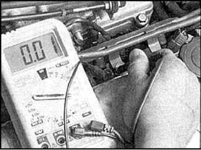
8. Check the resistance of the injectors.
9. For a more detailed check of the system, you need to contact specialists.