
Throttle body
Examination
1. Check the operation of the throttle linkage. Check that the throttle valve opens fully.
2. Inspect the throttle body for wear or deposits.
Replacement
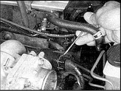
1. Remove the air supply pipe. Disconnect the accelerator cable.
2. Tag and disconnect all vacuum hoses.
3. Disconnect the throttle position sensor connector.
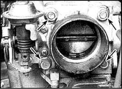
4. Remove the four mounting bolts and remove the throttle body and gasket.
5. Clean the throttle body and blow through all passages.
6. Installation is carried out in the reverse order of removal. Tighten the fixing bolts to the required tightening torque.
Diaphragm of the air valve of the air supply control system (only models with 1.8L engine)
Examination
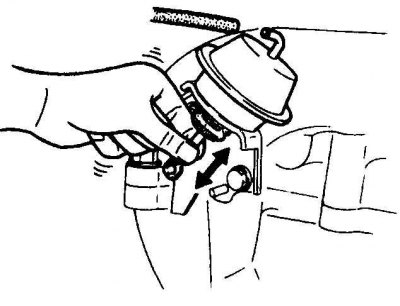
1. Check the stroke of the diaphragm rod. It should rise and fall smoothly.
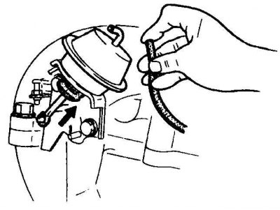
2. Check the supply of vacuum to the diaphragm and the operation of the diaphragm.
Throttle position sensor
Throttle Position Sensor Terminal Locations on Models After 1995
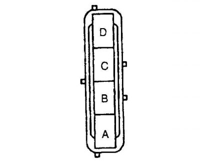 |  |
On 1990-1994 models, there should be no conductivity between the lower terminals of the sensor.
Examination
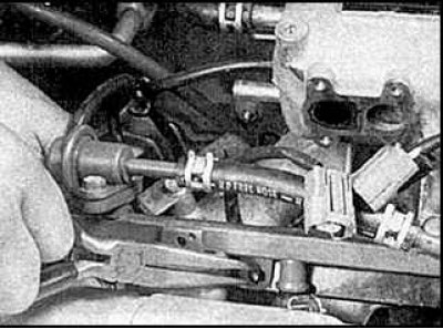
1. Insert feeler gauge:
- A) On models of 1990-1994 of release with an automatic transmission - 0.6 mm;
- b) On models of 1990-1994 of release with a manual transmission - 1.0 mm;
- V) On models after 1995 release - 1.3 mm
between stop screw and throttle stop lever (indicated by an arrow).
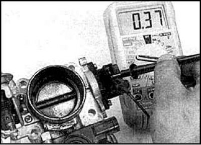
2. Check that there is no continuity between the sensor terminals.
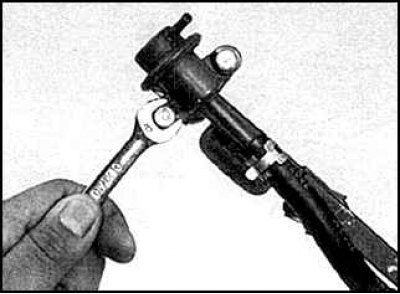
Adjustment
1. Connect an ohmmeter to the lower terminals of the throttle position sensor.
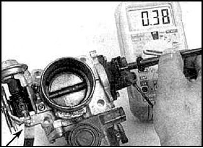
2. Loosen the two fixing screws of the sensor (indicated by arrows).
3. Insert a feeler gauge of the specified thickness between the stop screw and the stop lever:
- A) On models of 1990-1994 of release with an automatic transmission - 0.25 mm;
- b) On models of 1990-1994 of release with a manual transmission - 0.4 mm;
- V) On models after 1995 release - 0.15 mm
4. Rotate the sensor clockwise by 30°, then rotate it back until conduction occurs.
5. Insert a probe of the specified thickness and check that there is no conductivity:
- A) On models of 1990-1994 of release with an automatic transmission - 0.4 mm;
- b) On models of 1990-1994 of release with a manual transmission - 0.7 mm;
- V) On models after 1995 release - 0.5 mm.
6. If conductivity is present, readjust the sensor.
7. Tighten the two fixing screws.
8. If the sensor cannot be adjusted, replace it.
Replacement
1. Disconnect the connection connector, unscrew the fixing screws and replace the sensor.
2. Adjust the new sensor.
Fuel pressure control
Examination
See subsection 5.2.4.
Replacement
1. Disconnect the hoses from the regulator.
2. Unscrew the mounting bolts and remove the regulator from the fuel manifold.
3. At installation use a new sealing ring.
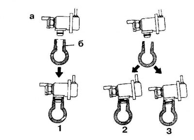
4. Install the fuel pressure regulator correctly:
- a - pressure regulator
- b - fuel pipe
- 1. Right
- 2. Wrong
- 3. Wrong
Idle Air Control Valve
Attention! To adjust the idle speed, you need to contact a specialist.
Examination
1. Check that the engine speed increases to about 1200 rpm when the valve is disconnected. If the speed does not increase, replace the valve.
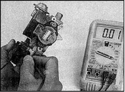
2. Disconnect the valve connector and measure the resistance between the valve terminals.
Replacement
1. Remove the throttle body.
2. Loosen the mounting screws and remove the valve and gasket.
3. Installation is carried out in the reverse order of removal. Use a new gasket.
Fuel manifold and injectors
Examination
See subsection 5.2.11.
Replacement
1. Disconnect the crankcase ventilation hoses from the cylinder head and intake manifold.
2. Loosen the hose clamps and disconnect the hoses.
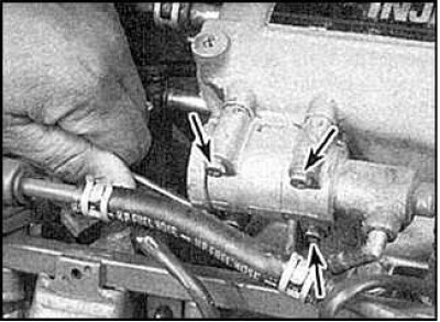
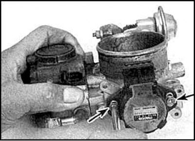
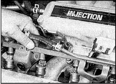
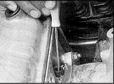
3. Loosen the air valve fixing screws (indicated by arrows).
4. Remove the air valve.
5. Mark injectors and connectors. Release the injector harness clamps.
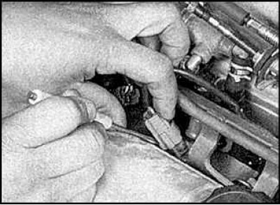
6. Disconnect the injector connectors.
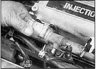
7. Disconnect the hoses from the pressure regulator and fuel manifold.
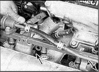
8. Loosen the fixing screws (indicated by arrows), that secure the fuel manifold to the intake manifold.
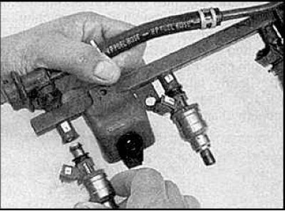
9. Remove the fuel manifold from the vehicle.
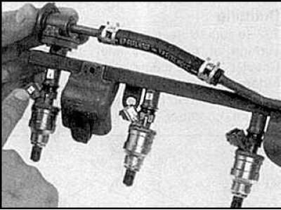
10. Number the injectors.
11. Remove injectors.
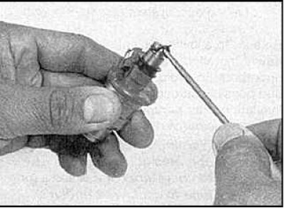
12. Remove the sealing ring.
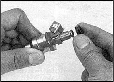
13. Remove the bushing from the top of the injector.
14. Remove the insulators from the holes in the intake manifold.
15. Installation is carried out in the reverse order of removal.
Air supply casing
Removing
1. Tag and disconnect all vacuum hoses.
2. Remove the throttle body.
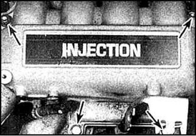
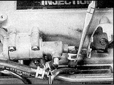
3. Loosen the top fixing bolts/nuts (indicated by arrows).
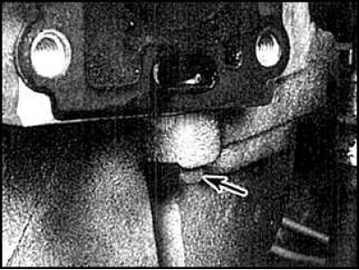
4. Loosen the bottom fixing bolt (indicated by an arrow).
5. Remove the cover.
Installation
Installation is carried out in the reverse order of removal.