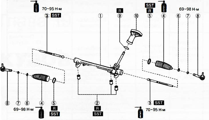
1. Steering gear.
2. Mounting sleeves.
3. Tie rods.
4. Anthers.
5. Large collars anthers.
6. Small collars of anthers.
7. Lock nuts.
8. Tie rod ends.
9. O-ring of circular cross-section.
10. Dust cover.
Note:
: replace the part with a new one after each removal.
: use a special tool or attachments.
: apply lubricant.
Attention. To prevent damage to the steering gear, clamp it in a vise using copper pads or a clean cloth.
The steering gear is assembled in the reverse order of disassembly, taking into account the following:
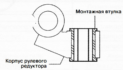
Installation of mounting sleeves
Apply a soapy solution to the rubber parts of the mounting sleeves, then press in the mounting sleeves (from below) into the steering gear housing using special tools to the position shown in the figure.
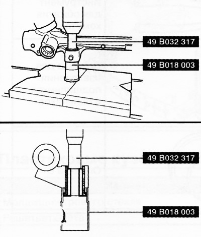
Note: Press in mounting sleeve (upper side) so that it partially enters the steering gear housing.
Turn the steering gear housing over, then press the mounting sleeve with special tools so that the sleeve of the mounting sleeve (upper side) hit the steering gear housing.
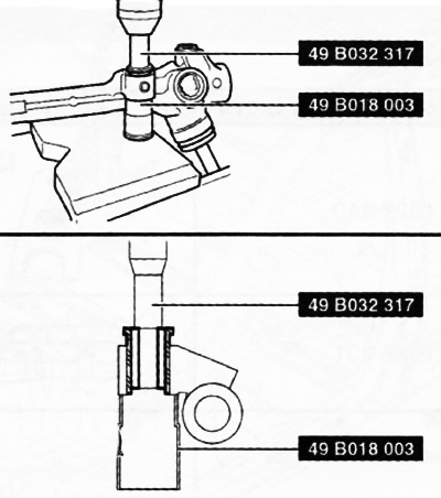
Make sure the mounting sleeve is properly seated with no gap between it and the steering gear housing as shown in the illustration. If there is a gap, correct the position of the bushing using special tools and a press.
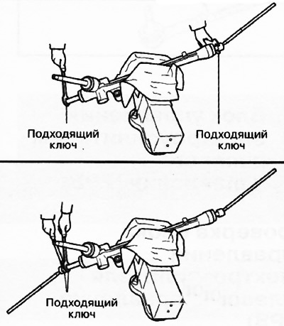
Tie rod installation
Fix the tie rod (from the steering gear) against turning with a suitable wrench, and tighten the tie rod with another suitable wrench.
Installing the boot clamps
Install the clamp on the boot.
Crimp the boot clamp with a special tool.
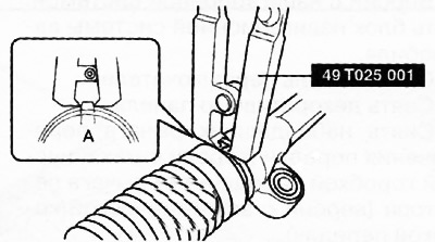
Make sure that the clearance of the embossed part A is correct (2.5-3.0mm). If gap A is too large, reduce the preset on the special tool and crimp the clamp again. If gap A is less than the norm, increase the preset on a special tool and, having removed the clamp, install and crimp a new one.
Trying to turn the clamp by hand, make sure that it is securely installed on the boot.
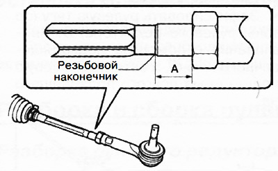
Installation of tie rod ends
Align the alignment marks made before removing the tie rod end, then install the tie rod end in place and tighten the lock nut to the specified torque.
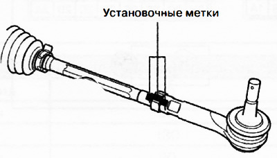
If there are no alignment marks, adjust dimension A shown in the figure to the standard value (10.1-23.1mm).