


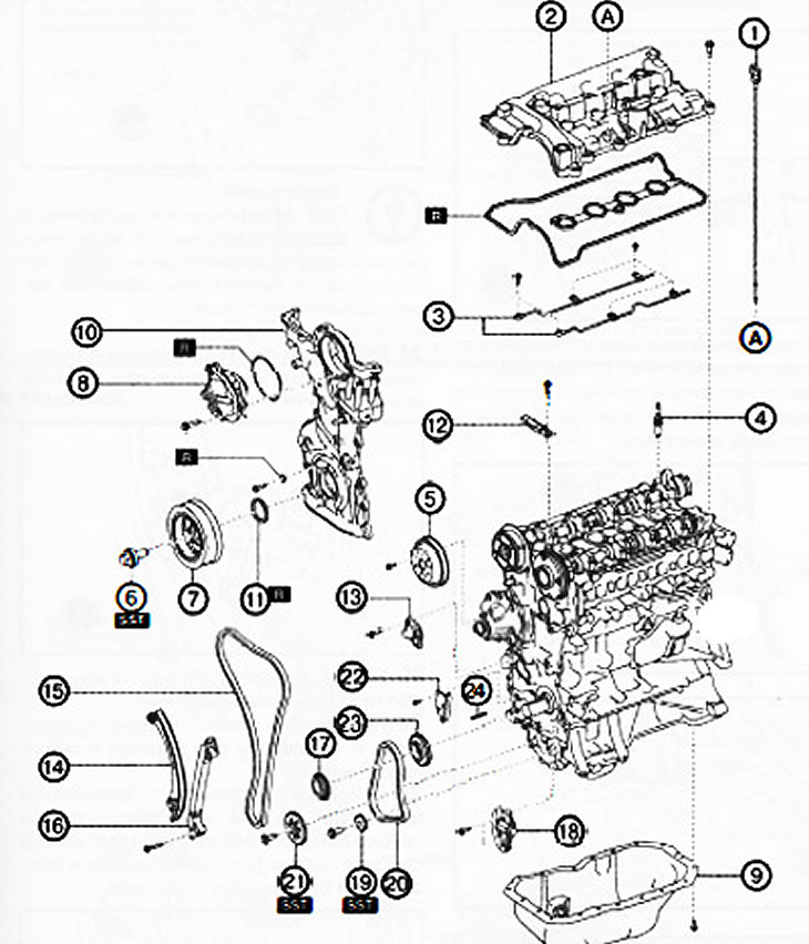
1. Oil dipstick.
2. Cylinder head cover.
3. Oil spray pipe.
4. Spark plugs.
5. Water pump pulley.
6. Crankshaft pulley bolt.
7. Crankshaft pulley.
8. Electric drive of the valve timing regulator.
9. Oil pan.
10. Engine front cover.
11. Front oil seal.
12. Drive chain damper No. 1.
13. Drive chain tensioner.
14. Tensioner shoe.
15. Timing chain drive.
16. Chain guide #2.
17. Crankshaft sprocket.
18. Oil pump drive chain tensioner.
19. Balance shaft sprocket.
20. Oil pump drive chain.
21. Oil pump driven sprocket.
22. Oil pump drive chain damper.
23. Oil pump drive sprocket. 24. Key.
Note:
: replace the part with a new one after each removal.
: use a special tool or attachments.
Attention.
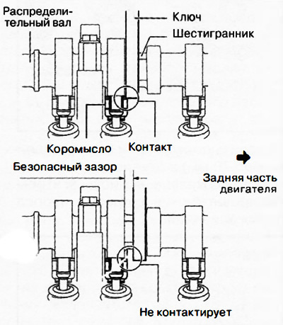
- If the camshaft is rotated after the timing chain has been removed, when the piston is at top dead center, the valves may hit the piston crown, causing engine damage. When rotating the camshaft with the drive chain removed, it is necessary to set all the engine pistons to the middle position.
- When turning the camshaft with a wrench on the hex part, the wrench may rest against the rocker and damage it. To prevent damage to the rocker arm, when holding the camshaft by the hex part, place the wrench closer to the rear of the engine, as shown in the figure, to ensure a safe gap between the wrench and the camshaft cam.
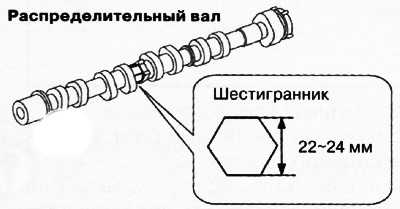
Note: The width of the hex part of the camshaft is 22-24mm.
1. Disconnect the negative battery terminal.
2. Remove the decorative engine cover.
3. Remove ignition coils/ion sensors.
4. Remove the front protective tray #2.
5. Remove mudguard.
6. Remove attachment drive belts.
7. Drain engine oil.
8. Remove the oil dipstick from the engine.
9. To turn away bolts of fastening and to remove a cover of a head of the block of cylinders with a lining.
10. To turn away bolts of fastening and to remove an oil-spraying tube from a head of the block of cylinders.
Attention. Be careful not to damage the grooves and surfaces of the water pump pulley when using tools, otherwise increased wear and damage to the drive belt, extraneous noise during operation, as well as damage to the pulley and rust may occur.
11. Align the hole in the water pump pulley with the hole in the pump housing as shown.
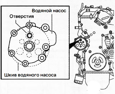
12. Insert a suitable bolt (approx. 70 mm long) into the water pump hole as shown in the figure to block the water pump pulley from turning.
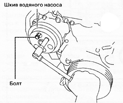
13. Remove the water pump pulley.
14. To turn away a fixing bolt and to remove a pulley of the water pump.
15. Remove the bolt used to block the pulley from turning.
16. Using a special device, fix the flywheel ring gear from turning.
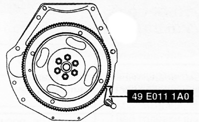
17. Remove the crankshaft pulley bolt.
18. Remove the crankshaft pulley.
19. To turn away fastening bolts and to remove the electric drive of a regulator of phases of gas distribution.
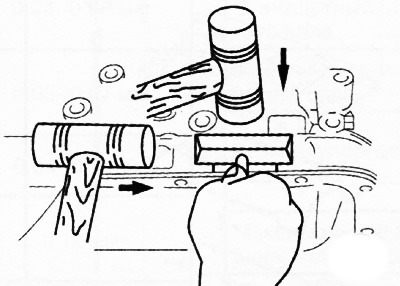
20. Loosen the mounting bolts and remove the oil pan, using a special cutter to cut the sealant between the pan and the cylinder block.
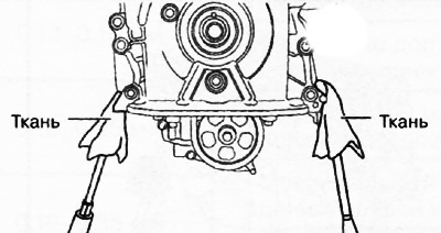
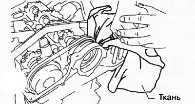
21. To turn away bolts of fastening of a forward cover of the engine. Using a cloth-wrapped screwdriver, loosen the sealant little by little and remove the engine front cover.
 |  |
Attention.
- Do not apply excessive force to the screwdriver. Otherwise, the engine front cover may be damaged.
- Be careful not to scratch or damage the contact surfaces. Otherwise, oil leaks may occur later.
22. Remove chain guide #1.
23. While moving the exhaust camshaft back and forth in the direction of the arrow in the figure, using a wrench installed on the hex part, press the drive chain tensioner plate with a screwdriver and release the plunger lock.
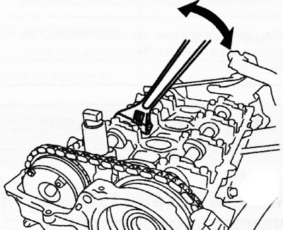 | 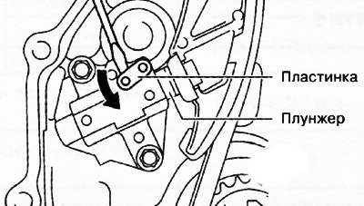 |
Note: When moving the exhaust camshaft back and forth, the drive chain will press the plunger into the tensioner, making it easier to move the plate.
24. Slowly press the plunger in the direction of the arrow in the figure with the plate pressed down.
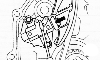
25. Remove the screwdriver from the record while continuing to press the plunger.
26. Gradually remove the force from the plunger and move it back and forth by 2-3 mm.
27. Insert a wire with a diameter of about 1.5 mm or rolled paper into the hole of the record and tensioner body to fix the record and block the plunger.
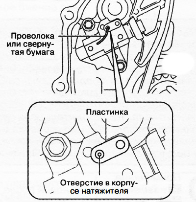
28. Remove the chain tensioner and tensioner shoe.
29. Remove the timing chain.
30. Remove damper No. 2 of the timing chain.
31. Remove the crankshaft sprocket.
32. Loosen the set bolts of the balance shaft sprockets and oil pump.
Note: At this point, you only need to loosen the set screws, not completely unscrew them. The bolts are removed after removing the oil pump drive chain tensioner.
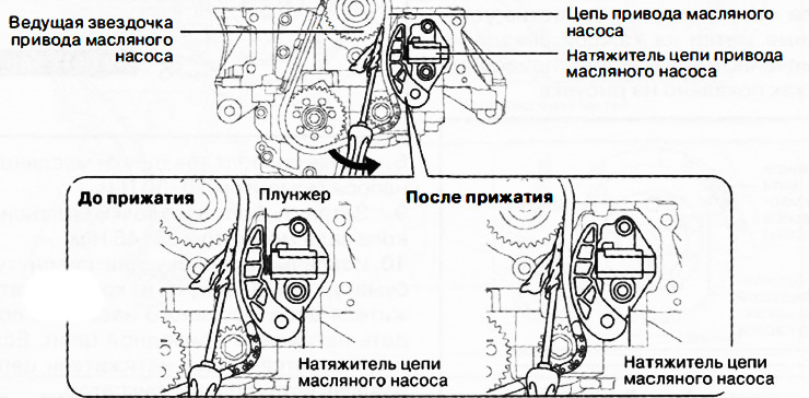
33. Insert a cloth-wrapped screwdriver into the gap between the oil pump sprocket and the drive chain as shown.
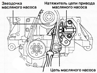
34. Moving the screwdriver in the direction of the arrow in the figure, press the oil pump drive chain against the tensioner and press the tensioner plunger.
35. With the plunger depressed, insert a wire with a diameter of approximately 1.4 mm or folded paper into the hole in the oil pump chain tensioner housing.
Note: Wire or rolled paper will hold the plunger, which will relieve tension on the drive chain.
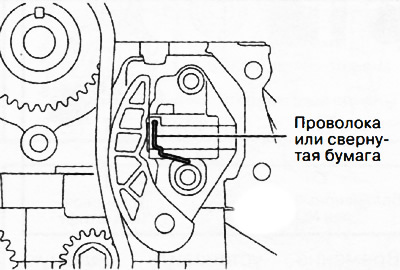
36. Remove the oil pump drive chain tensioner.
37. Remove the oil pump drive chain with the balancer shaft sprocket in one assembly.
38. Remove the oil pump sprocket.
39. Loosen the mounting bolts and remove the oil pump drive chain damper.
40. Remove the oil pump drive sprocket from the crankshaft.
41. Remove the key from the crankshaft.