


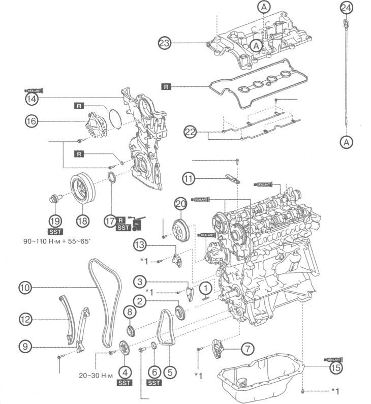
1. Key.
2. Oil pump drive sprocket.
3. Oil pump drive chain damper.
4. Oil pump driven sprocket.
5. Oil pump drive chain.
6. Balance shaft sprocket.
7. Oil pump chain tensioner.
8. Crankshaft sprocket.
9. Chain guide #2.
10. Timing chain drive.
11. Chain damper No. 1.
12. Tensioner shoe.
13. Timing chain tensioner.
14. Engine front cover.
15. Oil pan.
16. Electric drive of the valve timing regulator.
17. Front crankshaft oil seal.
18. Crankshaft pulley.
19. Crankshaft pulley bolt.
20. Water pump pulley.
21. Spark plugs.
22. Oil spray pipe.
23. Cylinder head cover.
24. Oil dipstick.
Note:
: replace the part with a new one after each removal.
: use a special tool or attachments.
: where to apply the sealant.
: apply oil.
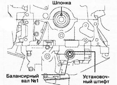
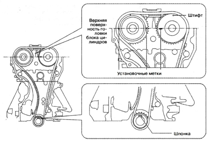
1. Verify that the crankshaft key and dowel pin are positioned as shown. If the location of these elements differs from that shown in the figure, rotate the crankshaft and balance shaft No. 1 so as to set the piston of the first cylinder to the top dead center position.
2. Temporarily install the driven sprocket of the oil pump and screw on its fastening bolts.
3. Align the marked links of the oil pump drive chain with the alignment mark of the balancer shaft sprocket.
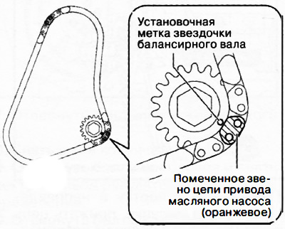
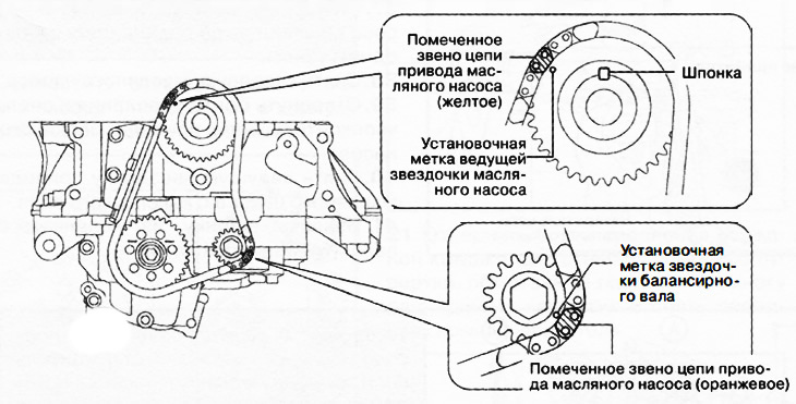
4. Install the oil pump drive chain with the balancer shaft sprocket in one assembly, aligning the match marks on each sprocket with the marked links in the drive chain as shown.
5. Install the balance shaft sprocket set bolt
6. Install the oil pump chain tensioner.
Attention. At this stage, do not remove the wire or rolled paper inserted into the oil pump chain tensioner housing.
7. Fix the flywheel ring gear with a special tool.
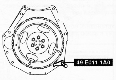
8. Tighten the oil pump sprocket bolt to 20-30 Nm.
9. Tighten the balancing shaft sprocket bolt to 38-46 Nm.
10. Remove the wire or folded paper inserted into the oil pump chain tensioner housing and tension the drive chain. If a new chain tensioner is used, remove the inserted retainer.
11. Install the timing gear sprocket onto the crankshaft.
12. Make sure that all alignment marks and crankshaft key are located as shown in the figure.
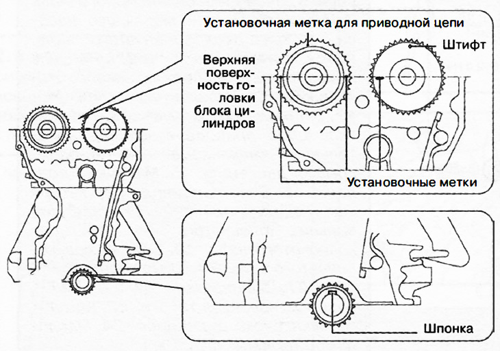
Note:
- The timing marks on the camshaft sprockets on the SKYACT/VG 2.5 engine are not completely parallel to the top surface of the cylinder head.
- If the alignment marks are not located as shown in the figure, turn the camshafts and crankshafts so that the piston of the first cylinder is at top dead center (TDC).
13. Install drive chain damper No. 2.
14. Install the timing chain, aligning the marks on the sprockets with the marked chain links as shown.
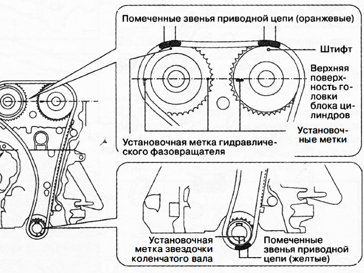
15. Install the tensioner shoe.
16. Install the timing chain tensioner.
17. After installing the chain tensioner, remove the wire or rolled paper inserted into the tensioner housing and tension the drive chain. If a new chain tensioner is used, remove the inserted retainer.
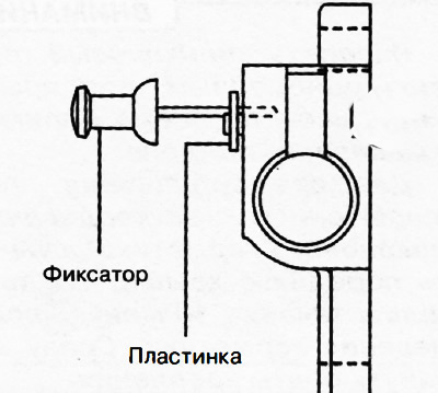
18. Install damper No. 1 of the timing chain.
19. Make sure that the timing chain has no slack and re-check the location of the alignment marks.
20. Rotate the crankshaft two full turns and check the timing again.
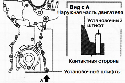
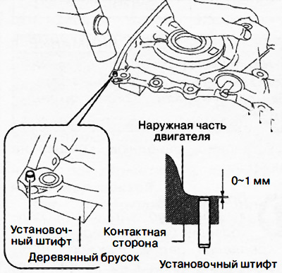
21. For a new engine front cover, the two locating pins shown in the illustration protrude outside the engine. Therefore, it is necessary to drive in these dowel pins with a hammer.
 |  |
22. Remove oil, dirt and sealant residues from the contact surfaces of the engine front cover, cylinder head and cylinder block.
Note: The timing marks on the SKYACTIV-G 2.5 camshaft sprockets are not completely parallel to the top surface of the cylinder head.
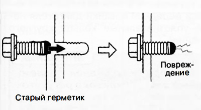
Note: When reusing the engine front cover mounting bolts, the remaining fixing compound must be removed from their threads.
Attention.
- Apply silicone sealant in an even, continuous bead.
- To prevent premature curing of the silicone sealant, install the front cover on the engine within 10 minutes of applying the sealant. Tighten the fastening bolts immediately.
- If the bolt with hardened sealant is tightened, it may cause a crack in the cylinder head or cylinder block.
23. Apply silicone sealant as shown.
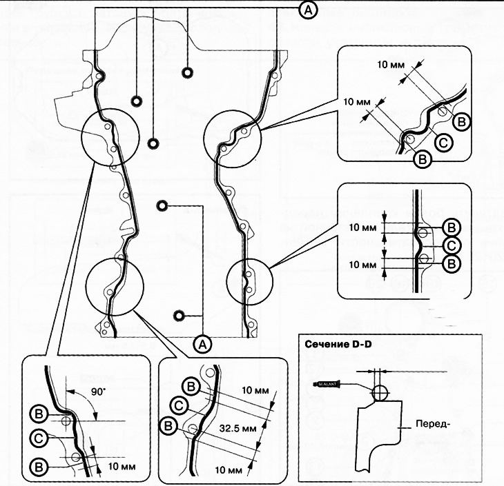
Sealant bead thickness:
A: 2-6mm, B: 4-6mm, C: 4-8mm
24. Apply sealant also to the areas indicated in the following figure.
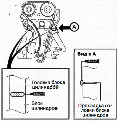
Attention. Apply silicone sealant so that it enters the cylinder head gasket.
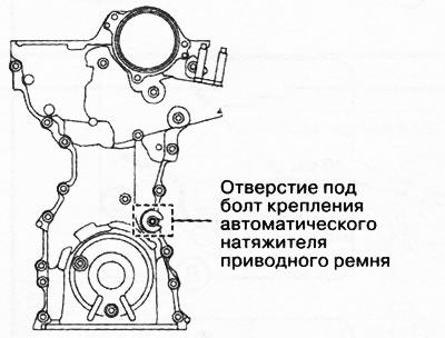
25. Install the front cover on the engine.
Note:
- Temporarily install a suitable bolt in the auto-tensioner mounting bolt hole to prevent sealant from entering the hole. Use an M8x1.25 bolt 40 mm long for this purpose.
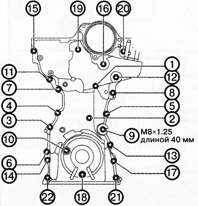
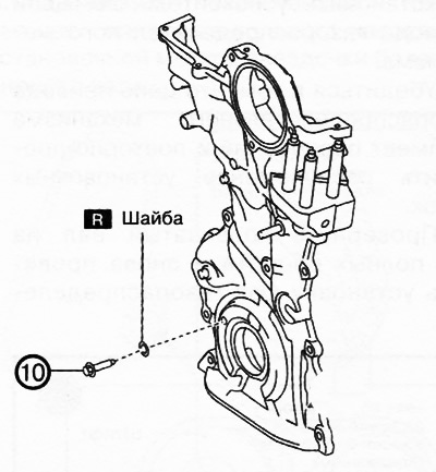
- Bolt #10 (following tightening sequence) must be installed with a new washer.
26. Tighten the engine front cover mounting bolts in the sequence shown in the figure to a torque of 20-26 Nm.
 |  |
Note:replace the part with a new one after each removal.
27. Remove the bolt installed in the bolt hole of the automatic tensioner.
28. Completely clean the contact surfaces of the cylinder block and oil pan from oil, sealant and other contaminants.
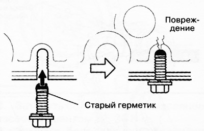
29. In case of reuse of the oil pan mounting bolts, remove the remnants of the old sealant from them.
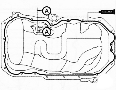
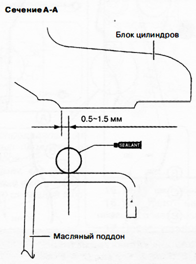
30. Apply silicone sealant to the oil pan from the inside of the bolt holes as shown. Sealant bead diameter: 3.0-7.0 mm.
 |  |
Attention.
- Apply silicone sealant in a uniform, continuous bead around the entire perimeter of the oil pan.
- To prevent premature curing of the silicone sealant, install the front cover on the engine within 10 minutes of applying the sealant. Tighten the fastening bolts immediately.
- If the bolt with hardened sealant is tightened, it may cause a crack in the cylinder head or cylinder block.
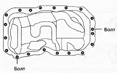
31. Install the oil pan on the cylinder block and install the two bolts shown in the figure.
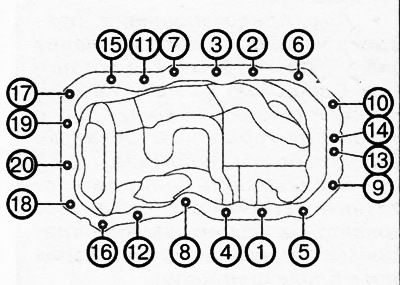
32. Tighten the oil pan mounting bolts in the sequence shown in the figure to a torque of 8-11 Nm.
33. Install new O-rings in the corresponding grooves in the engine front cover.
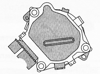
Attention. To prevent damage to the electric drive of the phase regulator, do not apply excessive force (100 N (10.2 kgf) or more) to the shaded areas in the figure.
Note:
- The eccentric shaft on the side of the electric phase regulator can rotate left and right.
- The electric drive of the phase regulator can be assembled with the connecting groove of the eccentric shaft located in any position. This does not affect the performance of the engine and does not cause any damage.
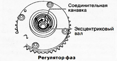
34. Before installation, rotate the protrusion of the end of the phase regulator electric drive so that it coincides with the connecting groove on the side of the phase regulator.
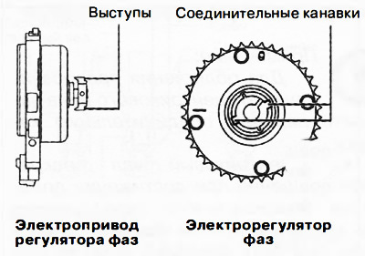
35. Connect the protrusions with the connecting grooves of the electric phase regulator and firmly install the electric drive on the cylinder head. Tighten the mounting bolts to 20-26 Nm.
36. Install the crankshaft pulley and tighten the pulley bolt in two steps:
- Stage 1: 90-110 Nm.
- Stage 2: pull up to an angle of 55-65°.
37. Install the water pump pulley and screw on the bolt.
38. Align the hole in the pulley with the hole in the water pump housing as shown.
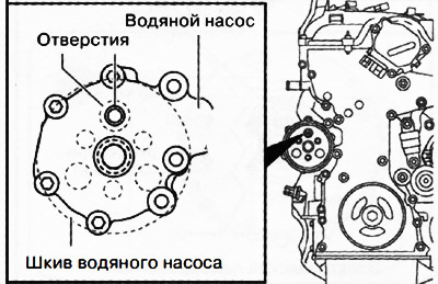
Attention. Be careful not to damage the grooves and surfaces of the water pump pulley when using tools, otherwise increased wear and damage to the drive belt, extraneous noise during operation, as well as damage to the pulley and rust may occur.
39. Insert a suitable 70mm bolt into the water pump hole as shown in the illustration to prevent the water pump pulley from turning. Fully tighten the water pump pulley bolt to 8-11 Nm.
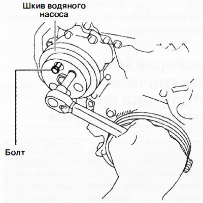
40. Remove the bolt inserted to secure the water pump pulley from turning.
41. Install the oil spray pipes and tighten the mounting bolts in the sequence shown in the figure.
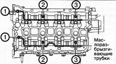 | 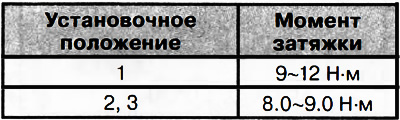 |
Attention.
- To ensure the tightness of the cylinder head cover, the following must be observed:
- Make sure the cylinder head cover gasket is inserted into the cover groove and install the cylinder head cover.
- Remove oil, dirt and sealant residues from the contact surfaces.
- To prevent premature curing of the silicone sealant, install the cylinder head cover on the engine within 10 minutes of applying the sealant and tighten the mounting bolts immediately.
42. Insert a new cylinder head gasket into the groove of the cylinder head cover.
43. Apply silicone sealant to the areas indicated in the figure.
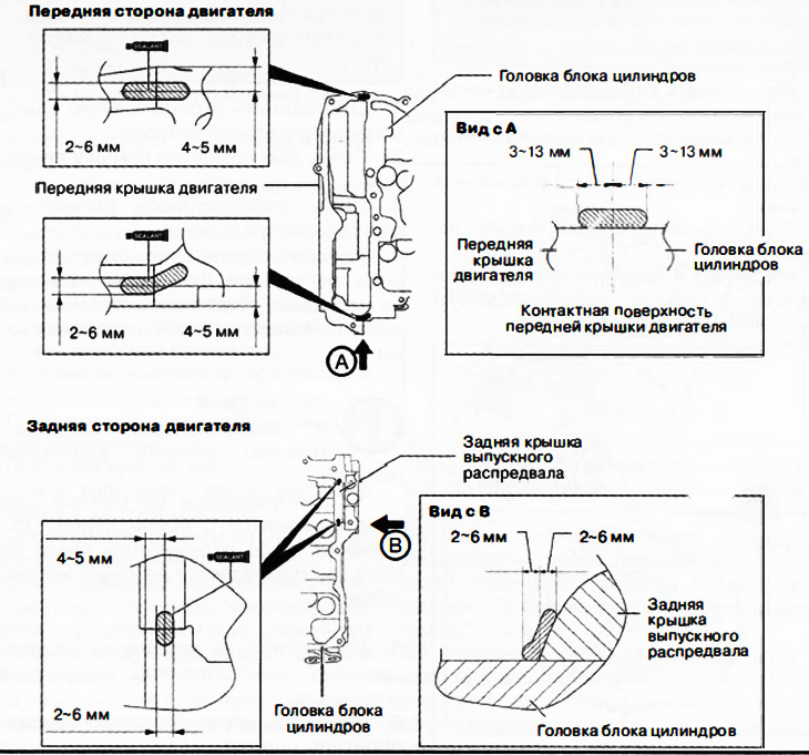
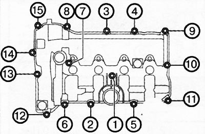
44. Tighten the cylinder head cover bolts in the sequence shown in the figure to a torque of 4.5-7.0 Nm.
45. Subsequent installation is carried out in the reverse order of removal.