


Contents: Carburetor ⇓ Automatic starting device ⇓ Idle and transition systems ⇓ Main dosing system ⇓ Accelerator pump ⇓
Carburetor
Aisan emulsion type carburetor, two-chamber, with sequential opening of throttle valves, with automatic starting device.
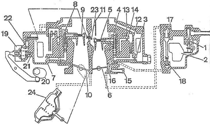
Aisan carburetor diagram: 1 - needle valve; 2 - float; 3 - main fuel jet of the 1st chamber; 4 - main air jet of the 1st chamber; 5, 9 - sprayers; 6 - 1st chamber throttle valve; 7 - main fuel jet of the 2nd chamber; 8 - main air jet of the 2nd chamber; 10 - 2nd chamber throttle valve; 11 - air damper; 12 - idle fuel jet; 13 - idle air jet; 14 - idle fuel channel; 15 - mixture quality (composition) adjustment screw; 16 - 1st chamber transition system gap; 17 - economizer channel piston; 18 - power mode economizer valve; 19 - diaphragm accelerator pump; 20 - accelerator pump drive cam; 21, 22 - check ball valves; 23 - accelerator pump nozzle; 24 - pneumatic drive of the throttle valve of the 2nd chamber.
Automatic starting device
Air damper 11 (see picture) is held in the closed position by a bimetallic spring 25 and a system of levers, the throttle valve of the 1st chamber is slightly open, i.e. it has a starting gap that corresponds to a reliable start of a cold engine.
When the engine starts, the vacuum in the cylinders creates a significant suction effect with a limited amount of air.
After the engine starts running, the vacuum in the intake manifold acts on the diaphragm of the pneumatic drive 26, which slightly opens the air damper 11 in order to enrich the combustible mixture at a minimum level when the engine warms up.
As the engine warms up, the air damper is opened by a bimetallic spring, which is heated by a resistor connected directly to the battery charging circuit.
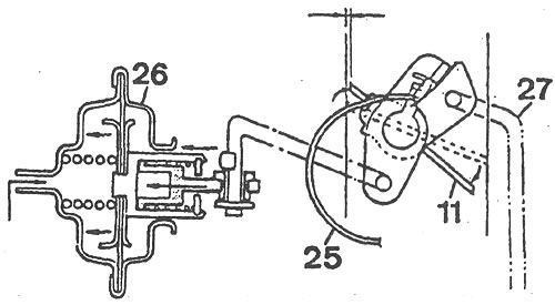
Automatic carburetor starter: 11 - air damper; 25 - bimetallic spring; 26 - pneumatic drive of the air damper; 27 - air damper opening thrust when engine speed increases.
Idle and transition systems
When the engine is idling, the throttle valve 6 of the 1st chamber is closed. The idle system takes fuel from the emulsion well after the main fuel jet 3 and supplies it to the idle fuel jet 12. At the outlet of this jet, the fuel is mixed with air passing through the air jet 13. The emulsion comes out under the throttle valve through the hole in the adjusting screw 15 of the quality (composition) of the idle mixture, while the quantity is determined by the amount of opening of the throttle valve 6 of the 1st chamber.
When the throttle valve is opened, the emulsion also enters through the gap of the transition system of the 1st chamber 16, which ensures a smooth transition from idle to load modes of engine operation. The 2nd chamber has only a transition system.
Main dosing system
Fuel is supplied through needle valve 1 to the float chamber, in which float 2, mounted pivotally on an axis, maintains a constant fuel level in the chamber.
From the float chamber, the fuel enters the emulsion well through the main fuel jet 3. When the throttle valve of the 1st chamber is open, a vacuum is created in its sprayer, under the action of which the fuel in the emulsion well rises and mixes with the air coming out of the hole of the emulsion tube, made integral with the main air jet 4. Through the sprayer 5, the fuel-air emulsion enters the diffusers and then into the mixing chamber of the carburetor.
When the throttle valve of the 2nd chamber is open, the operation of the main metering system of the 2nd chamber occurs in a similar manner.
The throttle valve of the 2nd chamber opens when the diaphragm of the pneumatic drive 24, which is connected by a rod to the throttle valve 10 of the 2nd chamber, moves under the action of the vacuum. Due to the presence of a mechanical lock, the throttle valve of the 2nd chamber opens only when the throttle valve of the 1st chamber is open and the engine is warm.
Accelerator pump
When the throttle valve of the 1st chamber is opened, cam 20, mounted on its axis, presses the lever and through the spring in the pusher acts on the diaphragm of the pump 19. Under pressure, fuel is injected into the 1st and 2nd chambers through the channel through the check valves 21 and 22 and the sprayers 23.
When the throttle valve of the 1st chamber is closed, fuel is sucked into the cavity of the accelerator pump from the float chamber. Check ball valves sequentially close the inlet and discharge channels.