


Disassembly
Remove the clamps securing the steering rod protective boots and slide the boots over the rods.
Turn the rack pinion until the limiting ring stops in the housing in one direction or another and clamp the steering gear in a vice with soft pads.
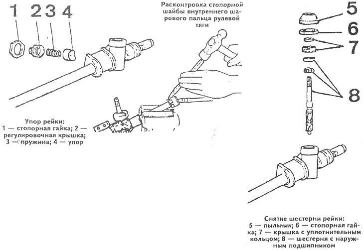
Bend back the tabs of the lock washer of the inner joint of the steering rod, unscrew the rod from the rack and remove the rod.
Turn the rack pinion until the stop ring stops in the housing in the opposite direction and remove the other steering rod in the same way.
Note: Before removing, mark the rods so that they can be returned to their original positions during assembly.
Remove lock nut 1 in sequence (see picture), adjusting cover 2, spring 3 and rack stop 4.
Remove the boot 5 (see picture) from the rack pinion, unscrew the lock nut 6, remove the gear cover assembly with the sealing ring 7, remove the gear 8 from the housing together with the outer ball bearing.
[The original article is available on: mazbook.ru]
Remove the rack from the steering gear housing in the direction opposite to the rack support sleeve.
Place the steering gear housing from the pinion seat side in a tank of water heated to approximately 80°C and remove the inner pinion bearing by tapping the housing with a mallet.
Remove both crankcase mounting brackets with rubber bushings.
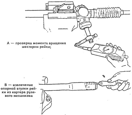
Remove the rack support sleeve from the side opposite the bearing seat using a hook, having first pressed the three locking petals on the crankcase tube (see picture).
Checking the technical condition
Before assembling the steering gear, check:
- condition of protective covers and rubber bushings of steering gear mounting brackets;
- degree of wear, absence of scoring, cracks on the rack and drive gear;
- asymmetry of wear of the working surface of the rack stop;
- play in the inner ball joints of the steering rods;
- clearance in the drive gear bearings and play in the rack support sleeve.
Note: In addition to the mandatory replacement of defective parts, the gear cover seal, the outer and inner bearings of the drive gear and the support sleeve of the rack should be replaced each time the steering gear is disassembled.
Assembly
Before installation, lubricate the contacting or rubbing parts with lithium grease.
Generously lubricate the inner pinion bearing and press it into the housing using the drive pinion.
Install the rack support bushing into the steering gear housing so that its profile matches the rack profile after its installation and so that the three locking tabs fit into the grooves.
Install two steering gear mounting brackets with rubber bushings.
Generously lubricate the rack teeth with lithium grease, carefully insert the rack into the steering gear housing from the side opposite the support sleeve.
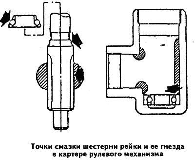
Lubricate the gear with the outer bearing pressed onto it and the bearing seat at the points shown in the figure using approximately 30 g of grease.
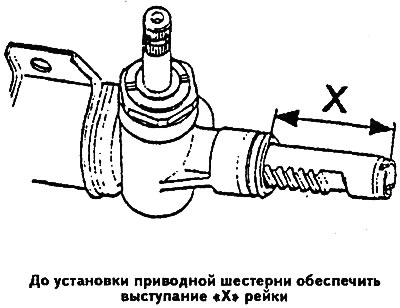
Extend the rack out of the steering gear housing so that it protrudes 66.7 mm (dimension "X" see figure) and install the drive pinion into the housing.
Install the drive gear cover with a new seal and tighten the cover to a torque of 7.0-9.0 kgf·m.
Screw on and tighten the drive gear cover lock nut to a torque of 8.0-10.0 kgf·m, then replace the dust cover.
Lubricate the rack stop and install it into the crankcase until it stops against the rack.
Install the spring, screw on the cover and adjust the rack stop in the following order:
- tighten the stop cover with a force of 10 kgf·m and loosen it;
- tighten the cap with a force of 3 kgf·m and unscrew it at an angle of 0-15°;
- tighten the cover lock nut with a force of 4.0-6.0 kgf·m;
- attach a dynamometer to the splined end of the rack drive gear and measure the gear rotation torque, which should be within 1.0-1.4 N·m;
- if the obtained value does not fit within the specified limits, loosen the lock nut and change the position of the stop adjusting cover until the required gear rotation torque is obtained;
- after adjustment, tighten the lock nut of the rack stop adjustment cover to a torque of 4.0-6.0 kgf·m.
Turn the rack gear until the limiting ring stops in the housing in one direction or another and clamp the protruding part of the rack in a vice with soft pads.
Install a new lock washer of the inner ball joint of the steering rod, install the rod and tighten its inner joint with a force of 8.0-10.0 kgf·m.
Bend the tabs of the tie rod ball joint lock washer.
Turn the rack gear until the stop ring stops in the housing in the opposite direction and install the other steering rod in the same way.
Install the rod protective covers in place and secure them with clamps.