


Contents: General information ⇓ Cylinder head of engines of models…⇓ Valves ⇓ Clearances in the valve drive…⇓ Cylinder head of the B6 EGI engine ⇓ Clearances in the Valve Drive…⇓
General information
The engine is four-stroke, four-cylinder, single-row. The engine is located in the front part of the body across the vehicle axis.
Main technical characteristics
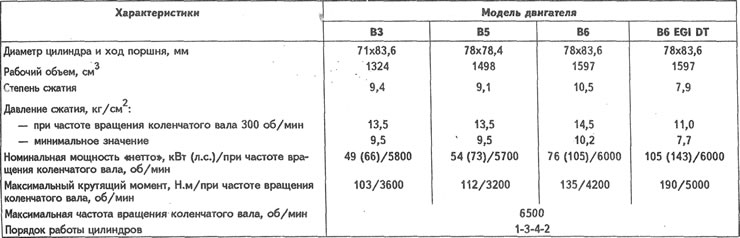
Cylinder head of engines of models B3, B5, B6
The cylinder head is cast from an aluminum alloy. The cylinder head of the B6 engine has multi-sphere combustion chambers, while the cylinder head of the B3 and B5 engines has wedge-shaped combustion chambers. The valve seats and guide bushings are pressed into the cylinder head. The camshaft support sockets are integral with the cylinder head. The rocker arm axle oil lines are insertable.
Head height along the parting planes, mm: 107.4-107.6.
Grinding tolerance, mm: 0.20.
Cylinder head surface warpage, no more than, mm: 0.15.
Valves
The valves are located in the cylinder head in a V-shape and are actuated by camshaft cams via rocker arms.
Valve characteristics
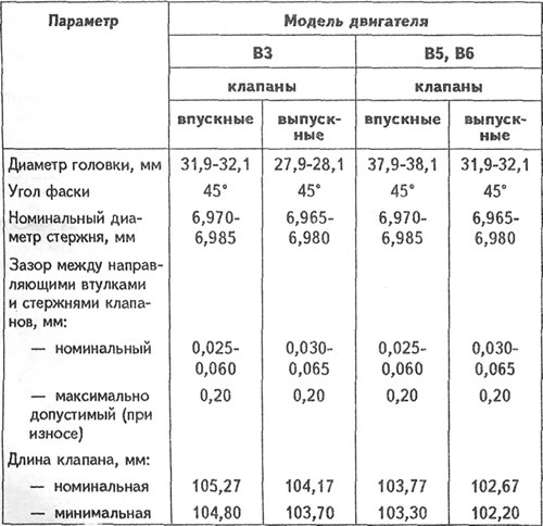
Clearances in the valve drive mechanism
Engine B6
The normal clearance between the ends of the rocker arm adjusting screw and the valve stem, measured with a feeler gauge on a hot engine, is 0.30 mm for the intake and exhaust valves.
B3 to B5 engines
Clearances in the valve drive mechanism are adjusted automatically by hydraulic tappets.
Valve seats
The valve seats are pressed into the cylinder head.
Working chamfer angle: 45°.
Working chamfer width, mm: 1.1-1.7.
Guide bushings
Inner diameter, mm: 7.01-7.03.
Valve springs
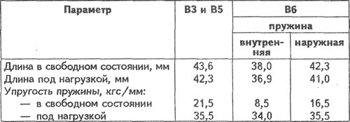
Each intake and exhaust valve of the B3 and B5 engines is equipped with one spring, while the B6 engine has two.
Inlet and outlet valve spring characteristics
Cylinder head of the B6 EGI engine
The cylinder head has four valves per cylinder and is cast from an aluminum alloy. It has wedge-shaped combustion chambers. The valve seats and guide bushings are insertable. In the upper part of the cylinder head there are five supports for the camshaft journals. The supports are detachable. The upper half is in the bearing housings, and the lower half is pressed into the cylinder head. The holes in the supports are machined together with the bearing housings, so they are not interchangeable.
Head height along the parting planes, mm: 133.8-134.0.
Grinding tolerance, mm: 0.20.
Cylinder head surface warpage, no more than, mm: 0.15.
Valves
The valves are arranged in a V-shape in the cylinder head and are actuated directly by the camshaft cams via hydraulic tappets.
Valve characteristics
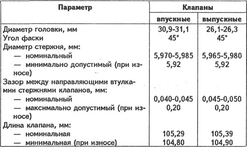
Clearances in the Valve Drive Mechanism
Valve clearances are compensated automatically by the oil pressure in the hydraulic tappets.
Valve seats
The valve seats are pressed into the cylinder head.
Working chamfer angle; 45°.
Working chamfer width, mm: 0.8-1.4.
Valve guide bushings
Inner diameter, mm: 6.01-6.03.
Valve springs
Each inlet and outlet valve is equipped with one spring. Spring length, mm:
- in free state: 45.6;
- minimum acceptable: 44.4.
Valve lifters
Clearance between tappets and cylinder head, mm:
- nominal: 0.07-0.08;
- maximum allowed: 0.18.