


Drive shaft with internal joint type "star" (tripod joint)
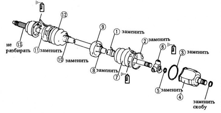
1 - cuff clamp; 2 - cuff clamp; 3 - bracket; 4 - hinge housing; 5 - retaining ring; 6 - tripod joint; 7 - cuff; 8 - clamp; 9 - counterweight only on the right side; 10 - cuff clamp; 11 - cuff clamp; 12 - cuff; 13 - outer joint with shaft. (If possible, do not disassemble, lubricate. Use the lubricant from the repair kit.)
Drive shaft with internal ball joint
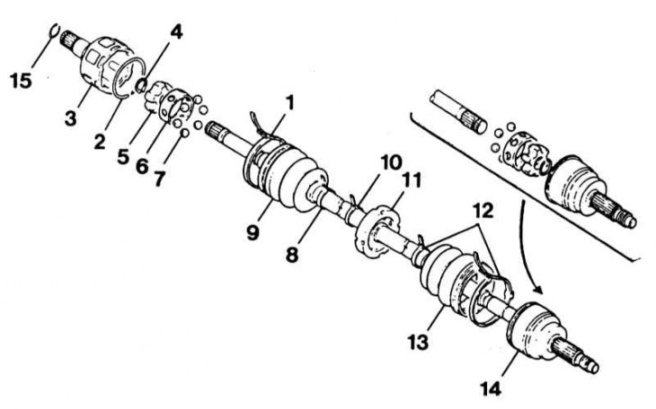
1 - cuff clamp; 2 - bracket; 3 - outer ring; 4 - retaining ring; 5 - inner ring; 6 - separator; 7 - balls; 8 - cuff clamp; 9 - cuff; 10 - cuff clamp; 11 - counterweight; Right side only:; 12 - cuff clamp; 13 - cuff; 14 - outer joint with shaft; If possible, do not disassemble.
Depending on the model, drive shafts are installed that differ in the internal joint: drive shafts with an internal ball joint are installed on cars up to 9/89 and on station wagon models with a manual transmission. Drive shafts with tripod joints are installed on cars from 10/89, except for station wagon models. All four-wheel drive vehicles have drive shafts with internal ball joints, in connection with an intermediate shaft for the right drive shaft.
Examination
1. Visually inspect the cuffs, replace faulty cuffs immediately. To replace the casings, the drive shaft must be removed and disassembled. Since the outer joint should not be disassembled, to remove its cuff, it is necessary to remove the cuff of the inner joint.
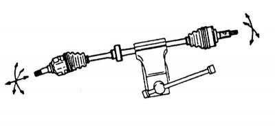
2. Clamp the removed drive shaft in a vice with gaskets and check the mobility of the joints.
3. Stretch and compress the outer hinge by hand, it should not have any play.
4. The inner tripod joint must move along the shaft.
5. Try to turn the inner joint on the shaft. It should not have any noticeable radial play.
6. If any faults are found during inspection, the drive shaft should be replaced.
Disassembling the drive shaft
1. Mark the edges of the joint seals on the shaft before removing them, this will make installation easier.
Original version of the article on the website: MAZBOOK
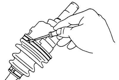
2. Remove the cuff clamps on the inner hinge using a screwdriver.
3. Move the joint cuffs on the shaft.
Drive shaft with internal tripod joint
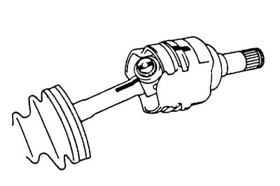
1. Before removing the housing, mark the position relative to the sprocket.
2. Mark the position of the shaft relative to the sprocket with a center punch, so that it is installed in its original place.
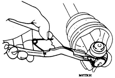
3. Compress and remove the sprocket retaining ring with suitable pliers.
4. Knock the sprocket off the shaft using a hammer and brass rod, without hitting the rollers.
Drive shaft with internal ball joint
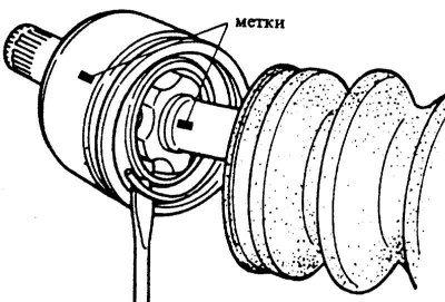
1. Before removing the shaft, mark its position relative to the outer race.
2. Pry up the locking clip with a flat screwdriver. Remove the inner hinge.
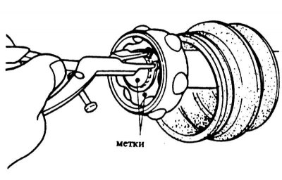
3. Compress the inner race retaining ring with suitable pliers and remove it. Use a center punch to mark the shaft so that it can be installed in its original position.
4. Knock the inner race off the shaft using a hammer and brass rod.
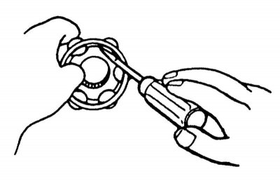
5. If necessary, disassemble the inner race. To do this, insert a narrow screwdriver between the inner race and the separator and push out the balls.
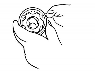
6. Mark the position of the separator relative to the inner race. Rotate the separator 30° and remove it from the inner race.
All drive shafts
1. Remove the inner joint seal from the shaft.
2. Right drive shaft: If equipped, loosen the counterweight clamp and remove the balancer.
Caution! Mark the position of the counterweight on the shaft so that it can be installed in its original place.
3. If faults are found on the outer hinge: Remove the outer hinge cuff through the inner hinge side, having first loosened the cuff clamps.
Attention! The outer hinge should not be disassembled.
4. Thoroughly wipe the internal cavities of the joint, internal parts, flanges, caps and cuffs. Remove old grease with solvent or compressed air. If dirt has penetrated into the joint, wash it.
5. Check the working surfaces for wear, replace the hinge if necessary.
Assembly
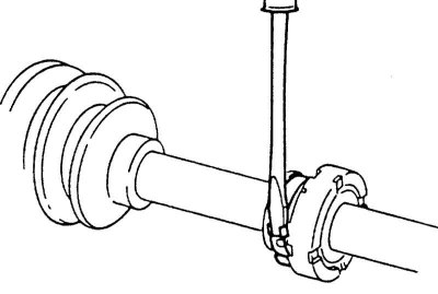
1. Replace cracked and faulty cuffs. In any case, all cuff clamps and retaining rings should be replaced.
2. Lightly lubricate the shaft surface so that the cuffs slide better. In addition, wrap the shaft splines with polymer tape so as not to damage the cuff when installing it.
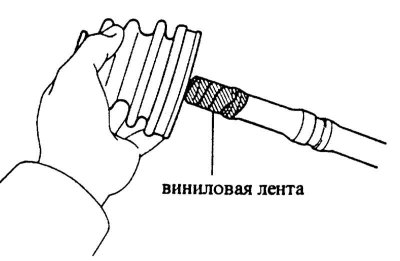
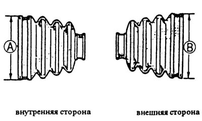
3. Put on the outer joint cuff with clamps, do not fasten the clamps yet. Do not mix up the joint cuffs: Select the cuff according to the outer diameter of the joint, the table applies to cars from 10/89 (except for station wagon models).
| Engine | diameter A, mm | diameter B, mm |
| 1.3 l. Diesel | 82,0 | 85,3 |
| 1.6 l | 85,9 | 80,8 |
| 1.9L SOHC | 84,0/80,01 | 89,0 |
| 1.9L DOHC | 89,9 | 85,2 |
1 - left drive shaft
Attention! The direction of installation of the clamps corresponds to the forward rotation of the shaft, i.e. the bent end of the clamps must face the direction of rotation of the shaft.
4. Right drive shaft: If present, install the counterweight, the mounting clamp should lie in the groove of the drive shaft. If there is no groove, align the counterweight according to the mark made during removal.
5. Put on the inner hinge cuff with clamps.
Drive shaft with internal tripod joint
1. Place the sprocket on the drive shaft, making sure that the marks made with the center punch match. Drive the sprocket onto the shaft with a hammer and brass rod. Do not apply force, but install the rod alternately on different points.
2. Insert a new retaining ring into the shaft groove.
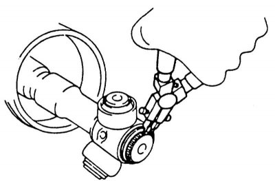
3. Fill the cavities of the outer hinge between the inner parts on both sides with special grease (black color). Make sure that as little grease as possible gets into the cuffs. Special grease is included in the MAZDA cuff repair kit. Distribute the entire amount of grease, approximately 80 g; 1.9L SOHC engine: 140 g.
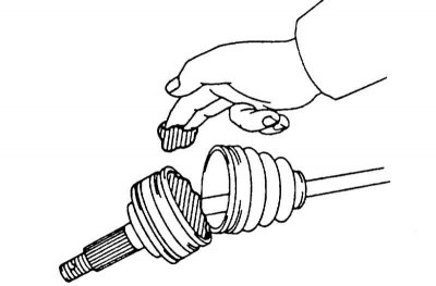
4. Distribute all the grease from the repair kit over the inner joint housing (yellow color). Amount of grease 130 g; except right drive shaft of 1.9L SOHC engine: 220 g.
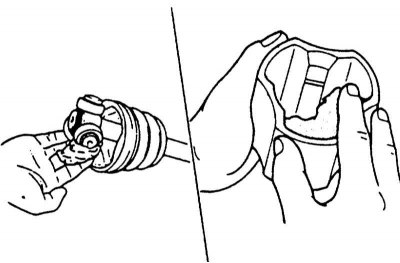
5. Insert the joint sprocket into the housing in the same position as when removing it and tighten the cuff.
Drive shaft with internal ball joint
1. Assemble the inner race with balls and separator in the reverse order of removal. The marks applied must match.
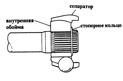
2. Place the inner race on the drive shaft, making sure that the marks made during removal of the center punch match. Insert a new retaining ring.
3. Insert the outer ring of the hinge and insert new locking bracket.
4. Fill the cavities of the outer hinge between the inner parts on both sides with special grease (black color) from the MAZDA repair kit. The amount of new grease compensates for the amount of grease removed. If all the old grease has been removed, all the grease from the repair kit should be used.
All drive shafts
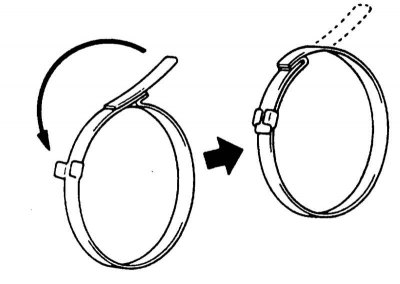
1. Secure the cuffs on the large diameter with clamps. The cuffs must sit securely in the grooves of the shaft. Bend the clamps of the cuffs with a screwdriver and secure by bending the fasteners.
2. Move the cuffs on the small diameter to the mark or groove on the shaft. The cuffs in the installed state should be neither stretched nor compressed.
3. Raise the cuff slightly at the small diameter with a small screwdriver to compensate for the pressure. Then tighten the cuff clamp and secure it.
4. Install the drive shaft.