


Attention.
- Incorrect handling of the SAS control unit may result in accidental deployment of the airbag modules and seat belt pretensioners, which may result in serious injury. Before working on the SAS control unit, read the service warnings.
- If the connector is connected and the ignition is turned on without properly securing the SAS control unit with the mounting nuts, the SAS control unit may detect an impact even with an accidental light touch, causing the airbag modules and seat belt pretensioners to deploy.
- If the DSC sensor initialization procedure is not completed, the dynamic stability control system will not function properly, which may cause an accident.
- Therefore, if the SAS control unit is replaced, it is necessary to initialise the DSC sensors to ensure proper operation of the system.
- If the SAS control unit is not configured after replacing it, the specific information will not be saved in the SAS control unit and the system will not operate normally.
- If the SAS control unit is replaced, it is essential to perform the configuration procedure before removing the SAS control unit. If the configuration is not performed or the SAS control unit is removed, fault code 80003:53 is displayed.
- To perform the configuration, it is necessary to read the vehicle-specific information from the old SAS control unit before replacing it. To do this, connect the M-MDS to the diagnostic connector and perform vehicle identification before removing the SAS control unit. The vehicle-specific information is temporarily stored in the M-MDS.
Note:
- The SAS control unit stores vehicle-specific information before replacement. The new SAS control unit does not have any vehicle-specific information.
- If the specific information from the old SAS control unit was not read before replacing it, the unit must be configured using the embedded data.
1. If the SAS control unit needs to be replaced, configure it.
2. Turn off the ignition.
3. Disconnect the negative battery terminal and wait at least one minute.
4. Remove the following parts:
- Front console box.
- Versions with manual transmission: gearshift knob.
- Shift Lever Panel.
- Top panel.
- Rear console.
5. Move the parking brake lever to the side so that it does not interfere with work.
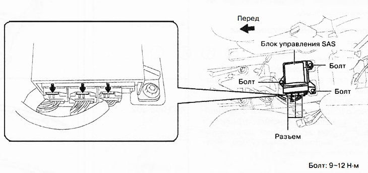
6. Disconnect the connectors.
7. Loosen the bolts.
8. Remove the SAS control unit.
9. Installation is carried out in the reverse order of removal.
10. Turn on the ignition (engine off or on).
11. Check that the air bag indicator flashes for 6 seconds and goes out. If the air bag indicator does not come on, perform an on-board self-diagnosis check of the system using the M-MDS.
12. Perform the initialization procedure for the dynamic stabilization system sensors.
Note: If configuration cannot be performed by writing previously read vehicle specific information, perform configuration using built-in information after replacing the SAS control unit.
SAS Control Unit Configuration
Using the read/save function
Note: When performing configuration, it is necessary to read the specific information from the SAS control unit before replacing it. Connect the M-MDS tool to the vehicle connector and perform vehicle identification before removing the SAS control unit from the vehicle. The vehicle specific information is temporarily stored in the M-MDS tool.
1. Connect the M-MDS device to the DLC-2 connector.
2. After identifying the vehicle, select the parameter "Module Programming" (module programming) from the M-MDS device home screen.
3. After this, select the parameters from the on-screen menu in the following sequence:
- Choose "Programmable Module Installation" (installing a programmable module).
- Select "RCM".
4. Perform the configuration according to the prompts on the screen.
Caution: When performing configuration, the CAN connection between the all-wheel drive control unit and other control units connected via the CAN bus may be temporarily interrupted, with the corresponding fault code appearing. After performing configuration, it is necessary to check for fault codes in the control units connected to the CAN bus and, if detected, delete these codes.
5. Check for fault codes in the control units connected to the CAN bus. If fault codes are detected, delete them. After deleting the codes, complete the procedure, since the configuration is complete. If fault codes are not deleted, search for the fault corresponding to the detected code.
Using built-in data
Note: If configuration is performed using embedded data, the personalization setting value is reset to the original value (factory delivery condition). After completing the configuration using the built-in data, you need to configure the personalization settings.
1. Connect the M-MDS device to the DLC-2 connector.
2. After identifying the vehicle, select the parameter "Module Programming" (module programming) from the M-MDS device home screen.
3. After this, select the parameters from the on-screen menu in the following sequence:
- Select "As-Built" (embedded data).
- Select "RCM".
4. Perform the configuration according to the prompts on the screen.
Caution: When performing configuration, the CAN connection between the all-wheel drive control unit and other control units connected via the CAN bus may be temporarily interrupted, with the corresponding fault code appearing. After performing configuration, it is necessary to check for fault codes in the control units connected to the CAN bus and, if detected, delete these codes.
5. Check for fault codes in the control units connected to the CAN bus. If fault codes are detected, delete them. After deleting the codes, complete the procedure, since the configuration is complete. If fault codes are not deleted, search for the fault corresponding to the detected code.