


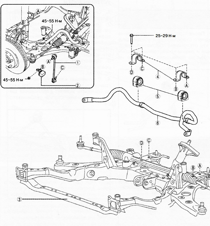
1. Stand of the front stabilizer bar.
2. Dynamic damper (if equipped).
3. Front subframe assembly.
4. Front anti-roll bar bracket.
5. Front anti-roll bar bushings.
6. Crossbar stabilizer bar.
Attention.
- Performing the following procedure without first removing the front ABS wheel sensor may cause an accidental open circuit in the wiring. Disconnect the front ABS wheel sensor wiring before performing the following procedures (from the drive shaft side) and secure the wiring in a suitable location where it will not be accidentally touched when servicing the vehicle.
- Fix the steering wheel with tape or wire to prevent the steering shaft from turning after disconnecting. If the steering wheel is turned after the steering shaft is disconnected from the steering gear, the internal parts of the contact disk may be damaged.
1. Remove the hinge cover (see chapter "Steering").
2. Disconnect the intermediate shaft from the steering gear (see chapter "Steering").
3. Disconnect the front ABS wheel sensor wiring from the steering knuckle and move it to the side.
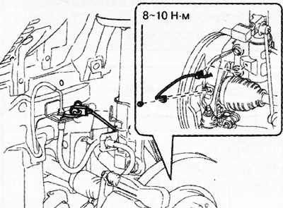
4. Loosen the upper nuts and disconnect the anti-roll bar struts.
5. If equipped, remove the dynamic dampers.
6. Remove the front subframe assembly (see below in this chapter).
7. Loosen the mounting bolts and remove the anti-roll bar with brackets from the subframe.
8. Having fixed the flange of the anti-roll bar bracket in a vice, remove the anti-roll bar bushing from the bracket.
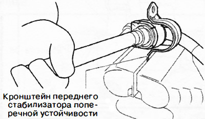
9. Remove the mounting bushings from the stabilizer bar.
10. Installation is carried out in the reverse order of removal, taking into account the following:
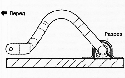
Install the bushings onto the front anti-roll bar so that the cuts in the bushings face the rear of the vehicle.
Manually install the bracket onto the front anti-roll bar bushing. If you cannot install the bracket onto the bushing manually, use a vice.
Attention.
- When using a vice to install the front anti-roll bar bracket, the bracket may become deformed.
- Install the cylindrical objects as shown in the figure so that the pressure is applied to the flanges of the front stabilizer bar bracket, then install the front stabilizer bar onto the stabilizer bar bushing.
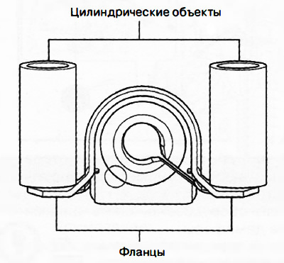 |
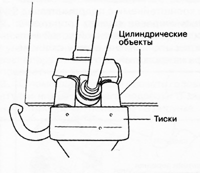 |
When installing the front stabilizer bracket, ensure that the deviation of the relative position of the bracket and bushing corresponds to the range shown in the figure.
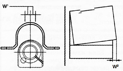
W1: no more than 0.5 mm
W2: no more than 2 mm
After installing the front anti-roll bar bracket, make sure that the bushing protrusion from the anti-roll bar bracket corresponds to the value shown in the figure.
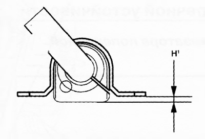
H2: no more than 13 mm.
After installing the front stabilizer bracket, make sure that the position deviation between the right and left stabilizer brackets does not exceed the value shown in the figure.
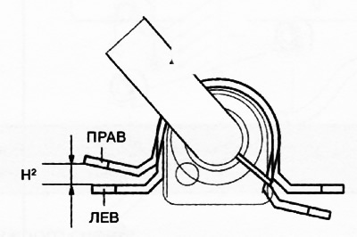
H2: no more than 6 mm.
Place the anti-roll bar with the bushings and brackets installed on a flat surface and make sure that the parameter shown in the figure corresponds to the standard.
The original article is available on MAZBOOK.RU
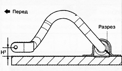
H3: no more than 32.1-42.1 mm.
Tighten bolts A and B as shown in the figure.
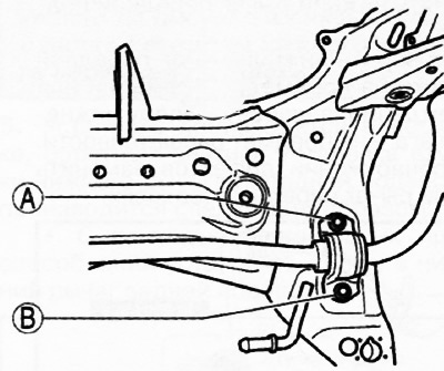
- Tighten bolt A to 25-29 Nm.
- Tighten bolt B to 25-29 Nm.
- Tighten bolt A again to 25-29 Nm.
11. After installing the front anti-roll bar, check the wheel alignment angles.