


Contents: Removal ⇓ Installation ⇓
Removal
1. Loosen the front wheel nuts. Raise the front of the vehicle and support it on jack stands. Remove the front wheels.
2. Remove the cross member installed under the engine compartment. IN chapter 7B the location of the beam mounting bolts and the procedure for removing it are described.
3. Remove the intermediate shaft support. IN chapter 7B the location of the support mounting bolts and the procedure for removing it are described.
4. Disconnect the electrical connector from the oxygen sensor (see chapter 6).
5. Unscrew the bolts securing the intake pipe(s) to the exhaust manifold (collectors) (see chapter 4) and move the pipe(s) to the side. Secure the pipe(s) with pieces of wire.
6. On models with a manual transmission, disconnect the shift linkage and extension (see chapter 7A). Secure the rod and extension with a piece of wire.
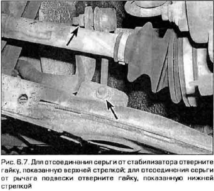
7. Remove both earrings from the stabilizer (figure 6.7).
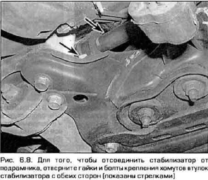
8. Unscrew the bolts of the stabilizer mounting clamps (figure 6.8).
9. Support the subframe with jacks and loosen the four bolts and two nuts securing the subframe. For this procedure, you will need one jack installed under the center of the subframe, or two jack stands that should be installed under the outer ends of the subframe.
Note: Do not lie under the subframe when removing it.
10. Remove the stabilizer by pulling it out from the right side of the car.
11. Inspect the rubber bushings and hinges of the earrings. If the bushings are damaged or worn, replace them. If there is play in the hinges, replace the earrings.
Installation
12. The stabilizer is installed in the reverse order of removal. Tighten all fasteners to the specified torque. Tightening torques for the cross member and intermediate shaft support fasteners are given in Technical data chapter 7. Tightening torques for subframe mounting bolts and nuts are given in Technical data this chapter.