


Wishbones
Front arms
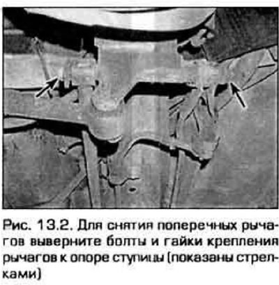
2. Turn out bolts of fastening of cross-section levers to a support of a nave (pic. 13.2).
3. Remove plastic covers from the central part of a back cross beam.
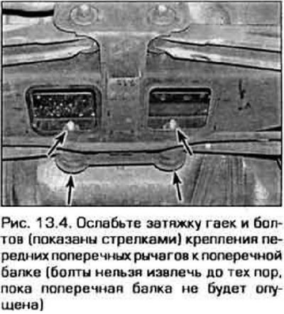
4. Loosen the tightness (but don't turn away) nuts and bolts for fastening the inner ends of the levers to the cross beam (pic. 13.4).
5. Mark position of a cross beam concerning the bottom of the car from both parties. This will help when adjusting the rear wheel alignment after assembly.
6. Place a jack under the cross beam, then unscrew the bolts securing the cross beam (two bolts on each side). Lower the beam so that the tie bolts of the control arms can be removed. Take out bolts and remove cross-section levers.
7. Installation is carried out in the reverse order of removal. Align the marks made before removal (see point 5), then tighten the cross member mounting bolts to the specified torque. Before tightening the transverse arm fasteners, place a jack under the hub support and slightly raise the support (so that the suspension takes approximately the working position). After that tighten fastenings of levers the demanded moment.
8. Lower the car and tighten the wheel nuts to the required torque (see technical data at the beginning of chapter 1).
Rear arms
9. Disconnect the anti-roll bar link from the rear transverse arm (see paragraph 12).
10. Turn out a bolt of fastening of the external end of the cross-section lever to a support of a nave (see fig. 13.2).
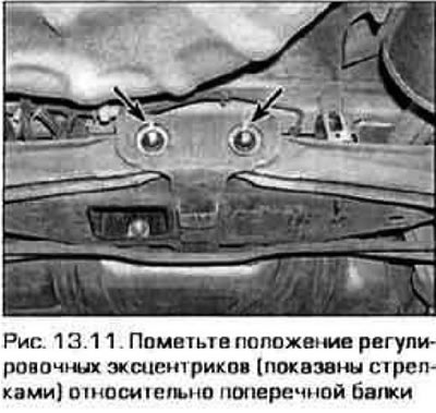
11. Mark the position of the eccentrics to adjust the convergence of the rear wheels relative to the cross beam (pic. 13.11).
12. Remove the plastic covers from the cross member, then remove the nut □ from the inner end of the arm. Remove the rear transverse arm.
13. Installation is carried out in sequence. reverse of removal Align the marks made before removal (see point 11). Before tightening the transverse arm mounting, place a jack under the hub support and slightly raise the support (so that the suspension takes approximately the working position). After that, tighten the lever mount to the required torque.
14. Lower the car and tighten the wheel nuts to the required torque (see technical data at the beginning of chapter 1).
15. After the repair is completed, contact a service station to adjust the rear wheel toe angle.
Trailing arms
16. Remove the bolts and disconnect the parking brake cables from the trailing arms.
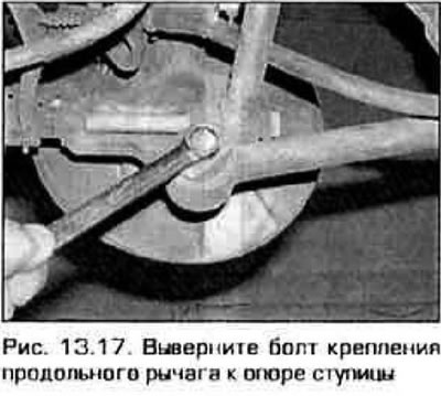
17. Turn out a bolt of fastening of the trailing arm to a support of a nave (pic. 13.17).
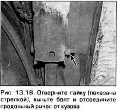
18. Turn away a nut and take out a bolt of forward fastening of the trailing arm (fig 13.18). Remove the trailing arm.
19. Installation is made in sequence, return to removal. Before tightening the longitudinal arm fasteners, place a jack under the hub support and slightly raise the support (so that the suspension hushed approximately the working position). After that tighten fastenings of levers the demanded moment.
20. Lower the car and tighten the wheel nuts to the required torque (see technical data at the beginning of chapter 1).