


Contents: Removal ⇓ Installation ⇓
Removal
1. Disconnect the wires from the battery (first negative, then positive).
Caution: If your vehicle's audio system is equipped with a theft deterrent, make sure you have the unlock code before disconnecting the battery.
2. Remove the air intake duct and air cleaner (see chapter 4).
3. Remove the starter (see chapter 5).
4. Disconnect the selector position sensor electrical connector and ground bus from the transmission. Unhook the wiring harnesses that are attached to the transmission from it.
5. Disconnect the wiring harness connector from the side of the transmission. On 4EAT and GF4A-EL transmissions the connector has a rectangular cross-section, and on CD4E and LA4A-EL transmissions it has an oval cross-section.
6. Disconnect the selector cable from the transmission (see paragraph 4).
7. Disconnect the electrical connector from the vehicle speed sensor.
8. Disconnect the coolant hoses from the transmission.
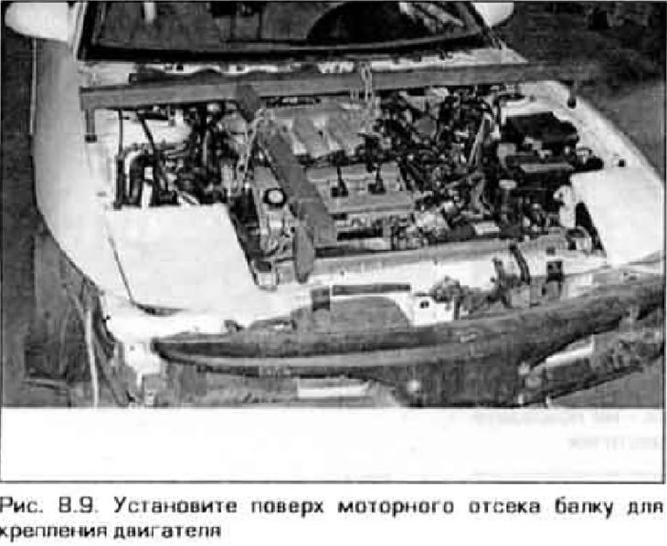
9. Raise the vehicle and place it on supports. Secure the engine to a beam mounted on top of the engine bay (figure 8.9). If there is no such device, the engine can be pulled up using a hoist. The engine must be securely supported while the transmission is removed from the vehicle.
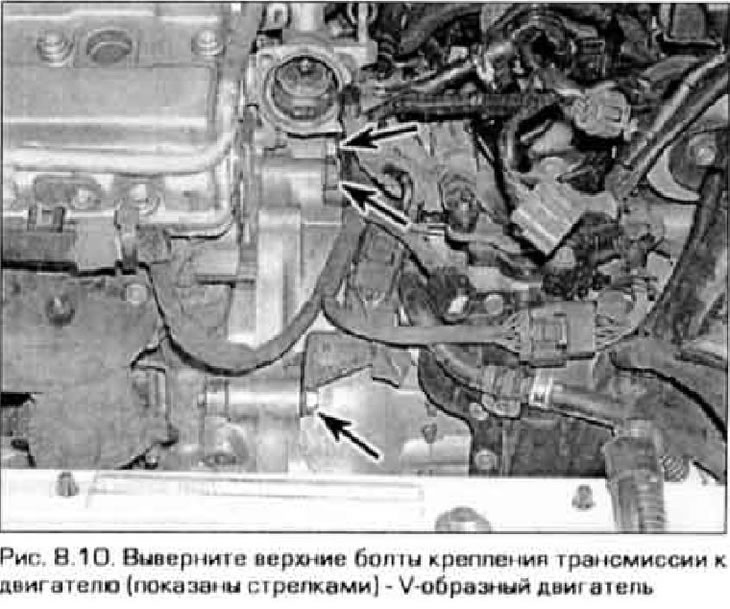
10. Unscrew the upper bolts securing the transmission to the engine (figure 8.10).
11. Remove the fuel filter bracket together with the filter and move them to the side.
12. Remove the left engine mount (see chapter 2A or 2B).
13. Remove the front wheels.
14. Drain the transmission fluid (see chapter 1).
15. On a 4-cylinder engine, remove the intake manifold support bracket.
16. Disconnect the steering rods from the steering knuckles.
17. Release the intermediate shaft support and disconnect the shaft from the transmission (see chapter 8).
Note: On a V-engine, remove the exhaust downpipe bolts from the exhaust manifold and lower the exhaust system.
18. Remove the right drive shaft together with the intermediate shaft from the transmission. Disconnect the left drive shaft from the transmission (see chapter 8). Place a plastic bag over the inner joint of the shaft to protect it from dirt.
19. Insert plugs or long thorium sockets into the transmission holes from which the shafts were removed to hold the differential axle gears in the installation position (see Figure 4.19,a and 4.19,b in Chapter 7A). There are special branded inserts for this purpose, however, if homemade plugs or thorium heads are well secured, they can serve as a completely suitable alternative. Please note: If this is not done and the axle gears become misaligned, the transmission will have to be disassembled.
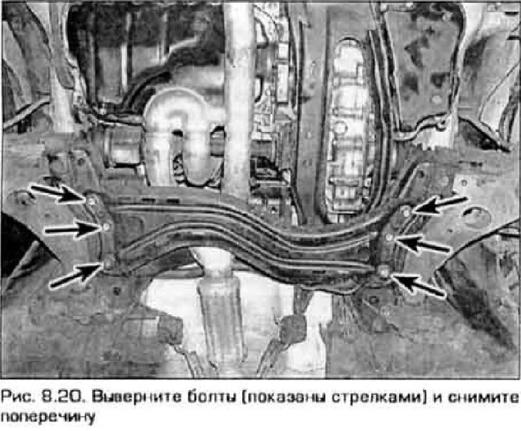
20. Remove the lower mudguard. Unscrew the six bolts securing the lower cross member and remove the cross member from the vehicle (figure 8.20).
21. On a V-engine, disconnect the electrical connectors from the left and right oxygen sensors (see chapter 6).
22. On engines with ABS, remove the wheel speed sensors and disconnect their wiring from the body parts.
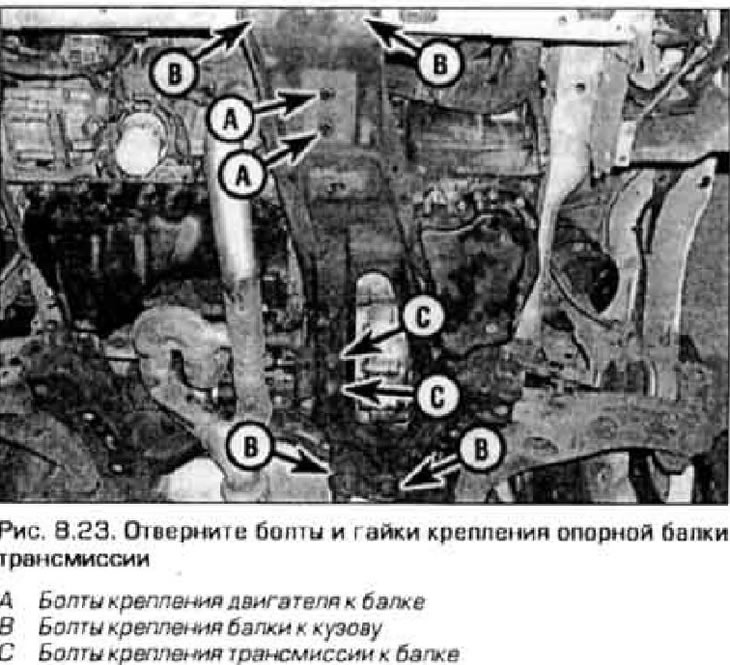
23. Mark the position of the transmission support beam relative to the body to facilitate subsequent assembly. Remove the six bolts and two nuts securing the transmission support beam and remove the beam (figure 8.23). When unscrewing the last bolt, support the beam so that it does not fall.
24. Unscrew the nuts securing the torque converter to the faceplate. To access the nuts on the CD4E/LA4A-EL transmission model, use the starter hole, and on the 4EAT/GF4A-EL models, remove the protective cover from the bottom of the transmission. As needed, turn the engine crankshaft to loosen each nut (typically, the torque converter is secured with four nuts).
25. Place a jack under the gearbox (for this purpose, it is preferable to use a special jack). If you are using a floor jack, place a block of wood between the jack and the transmission pan to protect the aluminum housing. Secure the gearbox to the jack using chains.
26. Remove the transmission support and support bracket. For more information on supports, see chapters 2A or 2B.
27. Remove the remaining transmission-to-engine mounting bolts.
28. Make sure again that all hoses and wires are disconnected from the transmission. Carefully move the transmission and jack away from the engine. Lower the transmission and pull it out from under the car.
29. After disconnecting the transmission, inspect the torque converter, its seals and other transmission seals (transmission side cover seal, speed sensor seal, etc.) for wear and damage. If necessary, replace the damaged seal.
Installation
30. If the torque converter was removed from the transmission, install it.
31. Install and secure the transmission on a jack dolly with a chain, roll it under the vehicle and lift it into the installation position. Carefully slide the transmission toward the engine, aligning the transmission dowel pins with the corresponding engine holes, as well as the bolt holes in the faceplate and torque converter. Do not apply excessive force when connecting the transmission to the engine. If the torque converter does not fit into place, adjust the transmission installation angle and align it with the engine.
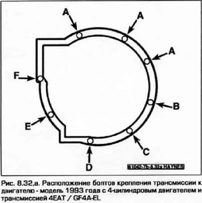
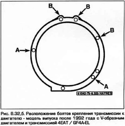
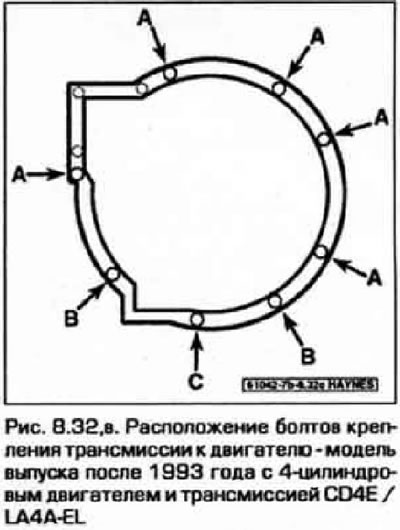
32. Screw in the transmission mounting bolts to the engine (figure 8.32, a-c).
- a) On 1993 4-cylinder engine models with 4EAT/GF4A-EL transmission, tighten bolts B, C, D, E, then F to the torque specified in Technical data at the beginning of the chapter.
- 6J On models with V-engine produced since 1993 and with 4EAT/GF4A-EL transmission, tighten bolts A to the specified torque.
- c) On models with a 4-stroke engine produced after 1993 and with a CD4E/LA4A-EL transmission, tighten bolts B and C to the specified torque.
 |
 |
33. Tighten the rear engine mount bracket bolts. For support installation details and bolt tightening torques, see. in the chapter 2A or 2B.
34. Install the lower left support onto the transmission. For support installation details and bolt tightening torques, see. in the chapter 2A or 2B.
35. Attach the selector cable to the transmission lever (see paragraph 3).
36. Install the transmission support beam. aligning it with the previously applied marks m. Tighten the beam fasteners to the specified torque (see Figure 8.23).
37. Install the cross member (see Figure 8.20) and tighten its bolts to the required torque.
38. Screw in the remaining transmission-to-engine mounting bolts (see Figure 8.32, a-c).
- a) On 1993 4-cylinder models with 4EAT/GF4A-EL transmission, tighten bolts A to the torque specified in Technical data at the beginning of the chapter.
- b) On models with a V-engine produced since 1993 and with a 4EAT/GF4A-EL transmission, tighten bolts B to the specified torque.
- c) On 1993 and newer 4-cylinder models with CD4E/LA4A-EL transmission, tighten bolts A to the specified torque.
39. Remove the plugs from the transmission outlet holes.
40. Install the intermediate and drive shafts (see chapter 8).
41. Connect the steering rods to the steering knuckles (see chapter 10).
42. Replace the lower mudguard, install the front wheels and lower the vehicle to the ground.
43. Screw in the bolts securing the front engine mount bracket (see chapter 2A or 2B).
44. Perform the remaining installation in the reverse order of removal.
45. Fill the transmission with the correct type of fluid (see chapter 1).
46. Take the car for a test drive to ensure that all vehicle systems are working properly. Check for leaks.
47. Loosen and retighten the power unit support fasteners.
48. Adjust the wheel alignment angles.