


Examination
1. Access to the sensor for inspection is possible from the engine compartment.
2. Disconnect the sensor electrical connector (figure 6.2).
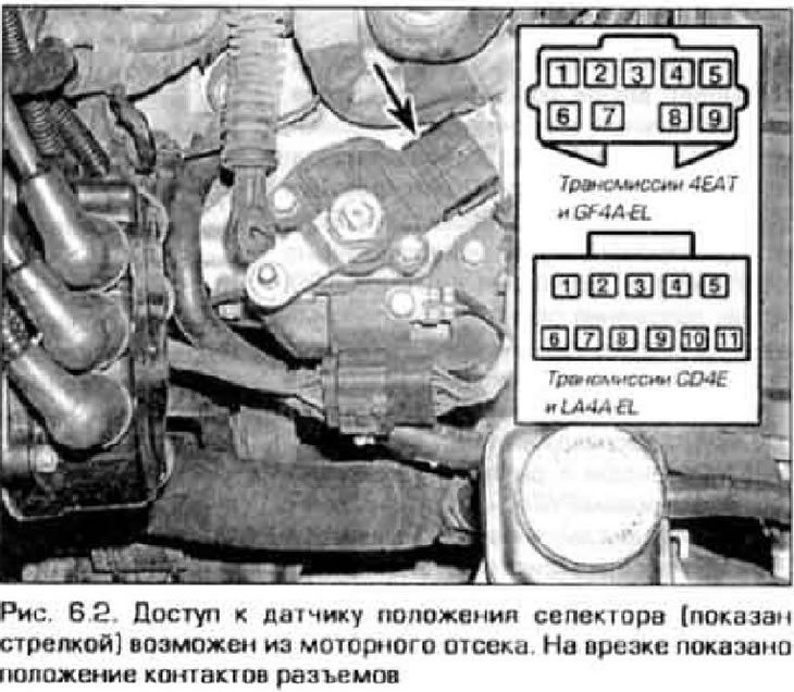
Note: The sensor on 4EAT and GE4AEL transmissions has a 9-pin connector, and on CD4EnLA4A-EL transmissions it has an 11-pin connector.
3. Move the selector lever alternately to each position and measure the resistance between the connector contacts indicated in the tables.
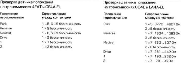
4. If the resistance between the contacts does not match the table, try adjusting the sensor (see below). If the sensor cannot be adjusted, replace it.
Adjustment (4EAT and GF4A-EL transmissions)
Note: A special tool is required for fine adjustment of the sensor on 4EAT and GF4A-EL transmissions.
5. Set the selector lever to the neutral position (Neutral). Disconnect the cable from the position sensor (see paragraph 4).
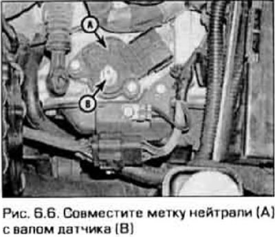
6. Slightly loosen the sensor mounting bolts. Turn the sensor to the Neutral position (figure 6.6).
7. Disconnect the sensor electrical connector and connect an ohmmeter to the contacts to check the Neutral position (see above for check tables). The ohmmeter should show infinity.
8. Tighten the brake caliper and attach the cable.
9. Go through all selector positions and check the resistance between the contacts. as specified in paragraphs. 1-4.
Replacement
10. Raise the vehicle and support it on stands.
11. Disconnect the electrical connector from the selector position sensor.
12. Set the selector lever to the Neutral position.
13. Unscrew the sensor mounting bolts and remove the sensor from the transmission.
14. Install the new sensor on the shaft.
15. Adjust the position of the sensor as indicated in paragraphs. 5-9 and tighten the sensor mounting bolts.
16. Make sure that the engine can only be started in the Neutral or Park positions.