


Caution! The models described in this manual are equipped with air bags. When working in the airbag area, always turn them off (see chapter 12) to avoid accidental activation, which could result in injury. The yellow wire harness that runs through the console and instrument panel is related to this system. Do not tamper with the airbag wiring or attempt to test it with any testing equipment.
Sheathing information
1. Models with automatic transmission are equipped with a locking system. The system consists of two subsystems: the starter lock and the ignition lock.
2. The ignition lock prevents the key from being removed unless the selector lever is in the PARK position. If the key is inserted while the selector lever is in a position other than PARK, an electromagnet is activated, preventing the key from being removed until the selector lever is moved to the PARK position.
3. The shift lock prevents the selector lever from being moved from PARK to REVERSE or DRIVE unless the brake pedal is depressed. The lever cannot be moved if the brake pedal is pressed simultaneously with the accelerator pedal. If the system malfunctions, the selector lever can be forced to unlock by inserting the key into the slot next to the selector lever (emergency lock switch).
4. The engagement lock system consists of: a selector position sensor, a lock actuator, a PARK position sensor, a brake pedal position sensor, a lock cable and an emergency lock switch. If the locking cable is broken or incorrectly adjusted, proceed to steps 25-39. The selector position sensor is located on the side of the transmission housing. The procedure for its removal and installation is described in paragraph 6. The actuator for the engagement lock is located under the center console next to the selector lever. The PARK position sensor is located next to the lock actuator. The method for checking the interlock system and the selector position sensor is given below in this paragraph. The brake pedal position sensor is located next to the pedal. The procedures for its verification and noticeability are described in chapter 6. If the emergency release switch is faulty, only a service station specialist can resolve the issue.
Examination
5. Below are simple tests of the ignition lock mechanism and the PARK position sensor. Testing these two system components means checking all ignition lock components, including the selector position sensor, lock cable, and brake pedal position sensor. If all test elements have completed successfully, but the lock does not work, further testing should be entrusted to service station specialists.
The article is reprinted from the portal [www.mazbook.ru]
Lock-on mechanism
6. Check the integrity of the MAIN (15 A) and STOP (20 A) fuses. Replace the fuses if necessary. If the fuses do not blow, check the connection from the interlock solenoid to the fuse panel. If the fuses are intact, check the actuator solenoid.
7. Remove the center console (see chapter 11).
8. Set the selector lever to the PARK position.
9. Loosen the four screws securing the lever position indicator (see figure 3.2). Raise the indicator.
10. Disconnect the 4-pin connector from the ignition lock actuator (figure 5.10).
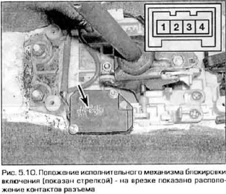
11. Measure the voltage at contact 2. With the ignition on and the engine not running, battery voltage should be present here. If there is no voltage, check the circuit from the connector to the ignition switch. To troubleshoot, please use the electrical diagrams at the end chapter 12.
12. Turn off the ignition. Battery voltage should now be present at terminal 1. If there is no voltage, check the circuit to the STOP fuse (20 A).
13. If voltage is present in both cases, proceed to the next test.
PARK position sensor
14. Remove the center console (see chapter 11).
15. Locate the 2-pin connector for the PARK position sensor (see figure 3.3).
16. Use thin probes to touch the connector contacts from the outside and measure the resistance between them. It should not show zero resistance (contacts are closed).
17. Depress the brake pedal and move the selector lever to the REVERSE position, then to all other positions. The sensor contacts must be open (the ohmmeter shows infinity).
18. Make sure that the locking mechanism disengages when the brake pedal is pressed and engages when released.
19. If the test gives different results, replace the PARK position sensor.
Replacement of system elements
Locking mechanism on
20. Remove the center console (see chapter 11).
21. Disconnect the 4-pin connector from the locking mechanism.
22. Unscrew the mechanism mounting bolts (figure 5.22).
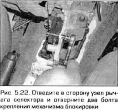
23. Remove the locking mechanism from the vehicle.
24. Installation is carried out in reverse order.
Ignition key lock cable
25. Remove the center console (see chapter 11).
26. Loosen the four screws securing the selector position indicator (see figure 3.2). Remove the indicator from the console.
27. Loosen the lock nut on the key lock cable housing (figure 5.27).
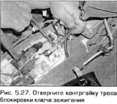
28. Remove the cable from the bracket.
29. Remove the lower instrument panel trim (see chapter 11).
30. Remove the upper and lower steering knuckle covers (see chapter 10).
31. Loosen the screw securing the cable bracket under the steering column and remove the bracket (figure 5.31).
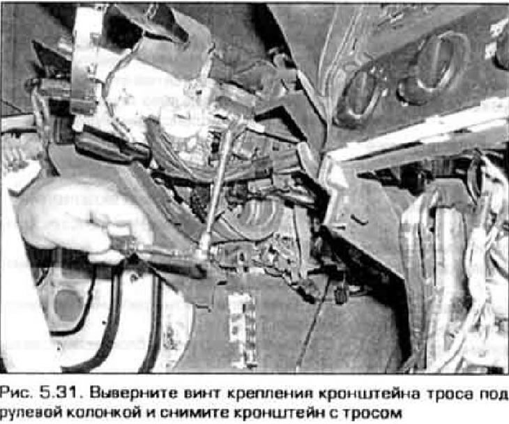
32. Disconnect the cable from the lock cylinder.
33. Remove the cable from the vehicle.
34. Install the cable under the steering column, connect it to the lock cylinder, secure the cable with the bracket and securely tighten the bracket mounting screw.
35. Install the instrument panel trim and steering column covers.
36. Install the cable onto the selector assembly bracket and tighten the lock nut.
37. Install the selector position indicator and secure it securely with screws.
38. Install the center console (see chapter 11).
39. Move the selector lever through all positions and make sure that the unit is assembled correctly.