
MazBook.ru
English Русский
Български
Беларускі
Український
Српски
Hrvatski
Română
Polski
Slovenský
Magyar
• Bookmark • Sitemap • Contacts •   
Cars Opel Cars Ford Cars Volkswagen Cars Audi Cars Kia Cars Renault Cars Peugeot


Familia Capella Mazda3 Mazda6 CX-? Others Articles
Capella 3 (1982-1992, petrol) Capella 3 and 4 (1982-1992) Capella 4 (1987-1992) Capella 5 (1991-1997) Capella 6 (1997-2005, petrol)

Powertrain Supports — inspection and replacement (Mazda Capella GF)

  • Home
  • Mazda Capella
  • Capella GF (1997-2005)
  • Power unit
  • 4-cylinder engines
  • Powertrain Supports — inspection and replacement
0
Contents: Examination ⇓ Replacement ⇓ Left support (from the driver's side) ⇓ Final tightening of all supports ⇓

Examination


1. When checking, the engine should be raised significantly to remove the load from its supports.

2. Raise the vehicle and support it on stands. Place a hydraulic jack under the engine, placing a wooden block on its head to avoid damaging the oil pan. Carefully lift the engine with a jack to relieve the load on the supports.

Caution! DO NOT work under the engine if it is supported only by a jack.


3. Inspect the engine mounts. First of all, pay attention to the rubber blocks - are there any cracks, separation from the metal base, or has the rubber hardened?. The destruction of the rubber block usually starts from the central hole.

4. Check for play in the supports. To do this, insert a strong screwdriver or crowbar into the support and rock the engine relative to the support. If play is evident, lower the engine and tighten the mount fasteners.

5. To reduce the likelihood of rubber decomposition, the supports should be coated with a protective compound.

6. Disconnect the negative battery cable, apply the parking brake, chock the wheels, raise the front of the car and place it on stands (if this has not already been done).

Caution: If your vehicle has a theft-protected audio system, make sure you have the unlock code before disconnecting the battery.


Replacement


Right support (from the passenger side)


7. The support supporting the power unit from the side of the timing mechanism drive is attached to the chassis of the unit. To replace the support, relieve it by lifting the engine from above using the lifting eye or supporting the engine from below with a hydraulic jack. To secure the pallet, place a wooden block on the jack head.


8. Unscrew the support clamp bolt, then the support mounting bolts to the chassis and pull out the rubber block (figure 16.8).
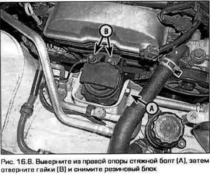
8. Unscrew the support clamp bolt, then the support mounting bolts to the chassis and pull out the…


9. Installation of the support is carried out in reverse order.

Note: Before final tightening of fasteners, lower the power unit and remove the supporting jack. If several supports were replaced, then the order of their final tightening see. below.


Front support


10. The front support is located between the engine and the radiator (figure 16.10).
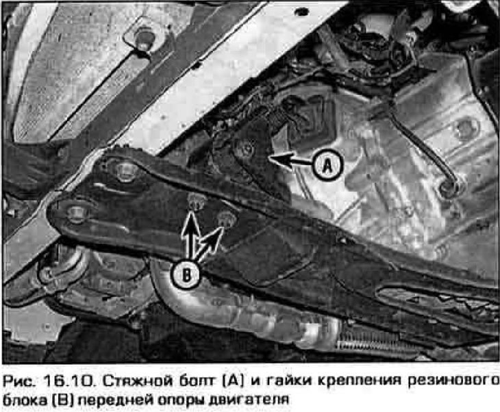
10. The front support is located between the engine and the radiator (figure 16.10).


11. To remove the front support, follow the steps in paragraphs. 7-9.

12. Installation is carried out in reverse order.

Note: Before final tightening of fasteners, lower the power unit and remove the supporting jack. If several supports were replaced, then the order of their final tightening see. below.


Rear support


13. If the intake manifold is not removed, access to this support will be difficult and is only possible from below. Release the tie bolt and lift the power block to remove the load from the support.

14. Unscrew the nuts securing the support to the subframe. unscrew the clamping bolt completely and pull it out, and lift the power unit so that it becomes possible to pull out the support (figure 16.14).
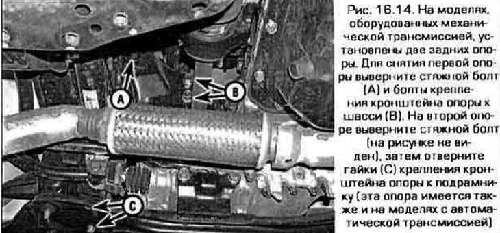
14. Unscrew the nuts securing the support to the subframe. unscrew the clamping bolt completely and…


15. Installation is carried out in reverse order.

The article is copied from the website (www.MazBook.ru)

Note: Before final tightening of fasteners, lower the power unit and remove the supporting jack. If several supports were replaced, then the order of their final tightening see. below.


Left support (from the driver's side)


Upper support


16. The driver's side support is attached to the top of the transmission and to the chassis (figure 16.16).
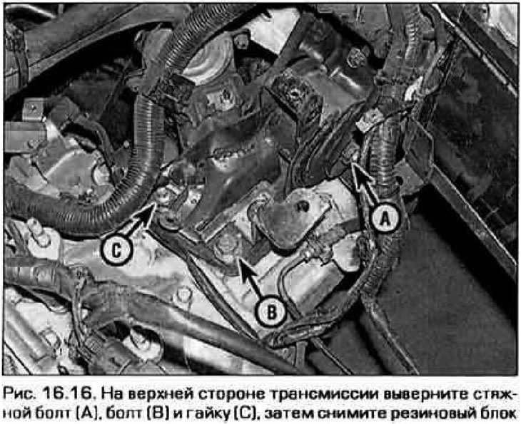
16. The driver's side support is attached to the top of the transmission and to the chassis (figure…


17. Support the power unit, unscrew the tie bolt, bolt and nut securing the support to the transmission and remove the support.


19. Install the support in reverse order.

Note: Before final tightening of fasteners, lower the power unit and remove the supporting jack. If several supports were replaced, then the order of their final tightening see. below.


Lower support


19. The lower support connects the transmission to the subframe (figure 16.19).
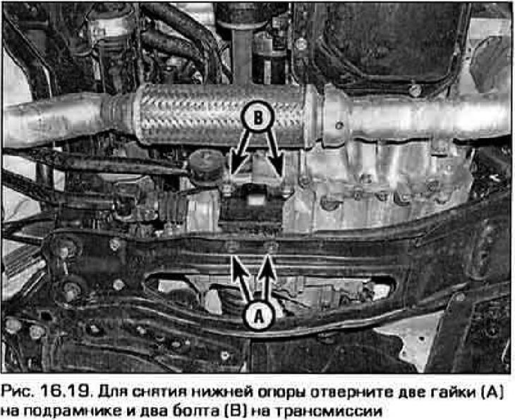
19. The lower support connects the transmission to the subframe (figure 16.19).


20. Support the power unit. Unscrew the two bolts securing the support to the transmission and the two nuts securing it to the subframe.

Final tightening of all supports


21. When final tightening of all supports, the vehicle should stand horizontally, and the weight of the power unit should rest on the supports. Fill the threaded connections with anti-loosening compound. Tighten all fasteners on all supports first by hand, then gradually tighten them until the required torque is reached.
This article is available at: russian, bulgarian, belarusian, ukrainian, serbian, croatian, romanian, polish, slovak, hungarian
This text was checked by: German Vorobyov
Share with friends on social networks:

Previous
Capella 6 » 4-cylinder engines
Next

Rear crankshaft oil seal — removal and installation
Flywheel (faceplate) — removal and installation
Oil pump — removal, inspection and installation
Oil pan — removal and installation
Front Crankshaft Oil Seal — replacement
More articles on repairing other Mazda models
Powertrain suspension Mazda Familia 5 (1985-1989)
Link in different formats to this article
Comments and feedback from visitors
No comments yet


How much will 12 + 27 ?


Capella 6 (1997-2005, petrol) 
  • General information
  • Introduction to guide
  • User manual
  • Troubleshooting
  • Maintenance
  • Power unit
  • 4-cylinder engines
  • 6-cylinder engines
  • Engine overhaul
  • Cooling and ventilation
  • Power and exhaust systems
  • Engine electrics
  • Control system
  • Transmission
  • Mechanical gearbox
  • Automatic gearbox
  • Clutch and drive shafts
  • Chassis
  • Brake system
  • Car suspension
  • Steering
  • Body
  • Exterior (external elements)
  • Interior (internal elements)
  • Doors, windows and locks
  • Electrical equipment
  • Equipment and devices
  • Electrical circuits
Capella 5 (1991-1997) 
  • General information
  • User manual
  • Maintenance
  • Helpful hints
  • Power unit
  • Petrol engines 1.6 and 1.8
  • Petrol engines 2.0
  • 2.5 petrol engines
  • Overhaul engines 1.6 and 1.8
  • Overhaul engines 2.0 and 2.5
  • Diesel engine 2.0
  • Engine electrics
  • Cooling system
  • Air conditioner
  • Carburetor Nikki 30/34
  • Power system (1.6 and 1.8)
  • Power system (2.0 and 2.5)
  • Control system
  • Transmission
  • Mechanical gearbox
  • Automatic gearbox
  • Clutch and axles
  • Chassis
  • Brake system
  • Suspension and wheels
  • Steering
  • Body
  • Exterior (external elements)
  • Interior (internal elements)
  • Doors and windows
  • Electrical equipment
  • Equipment and devices
  • Electrical circuits
Capella 4 (1987-1992) 
  • General information
  • Introduction to manual
  • Vehicle specifications
  • Power unit
  • Engine repair
  • Lubrication system
  • Cooling system
  • Fuel system (carburetor)
  • Fuel injection (FE)
  • Fuel injection (DOHC)
  • Fuel system (diesel)
  • Ignition system
  • Transmission
  • Clutch
  • Gearbox
  • Drive shafts
  • Chassis
  • Front suspension
  • Rear suspension
  • Steering system
  • Brake system
  • Electrical equipment
  • Equipment and devices
  • Electrical circuits
Capella 3 and 4 (1982-1992) 
  • General information
  • User manual
  • Maintenance
  • Power unit
  • Gasoline engine
  • Engine overhaul (gasoline)
  • Diesel engine
  • Cooling and heating
  • Supply system
  • Ignition system
  • Emission reduction
  • Transmission
  • Clutch
  • Mechanical gearbox
  • Automatic gearbox
  • Drive shafts
  • Chassis
  • Brake system
  • Suspension and wheels
  • Steering
  • Body
  • Exterior (external elements)
  • Interior (internal elements)
  • Electrical equipment
  • Equipment and devices
  • Power devices
  • Electrical circuits
Capella 3 (1982-1992, petrol) 
  • General information
  • User manual
  • Maintenance
  • Troubleshooting
  • Late models
  • Power unit
  • Engine in car
  • Engine overhaul
  • Cooling and heating system
  • Fuel and exhaust system
  • Engine electrical system
  • Emission control system
  • Transmission
  • Mechanical gearbox
  • Automatic gearbox
  • Clutch and drive shafts
  • Chassis
  • Brake system
  • Suspension and wheels
  • Steering
  • Body
  • Exterior (external elements)
  • Interior (internal elements)
  • Electrical equipment
  • Equipment and devices
  • Lighting and lamps
  • Electrical circuits
MazBook.ru © 2018–2026 · Mobile version · Articles and news · Sitemap: EN BG BY UA RS HR RO PL SK HU · Feedback · Site search · Add to bookmarks Familia 5 (BF) · Familia 6 (BG) · Capella 3 (GC) · Capella 3 and 4 (GC) · Capella 4 (GD) · Capella 5 (GE) · Capella 6 (GF) · Mazda3 BK · Mazda6 GG · CX-5KE · Mazda 121 (3) · Mazda BT-50 (1) ·
By continuing to use the site, you agree to the use of cookies 🔐