MazBook.ru
English Русский
Български
Беларускі
Український
Српски
Hrvatski
Română
Polski
Slovenský
Magyar
• Bookmark • Sitemap • Contacts •   
Cars Opel Cars Ford Cars Volkswagen Cars Audi Cars Kia Cars Renault Cars Peugeot


Familia Capella Mazda3 Mazda6 CX-? Others Articles
Capella 3 (1982-1992, petrol) Capella 3 and 4 (1982-1992) Capella 4 (1987-1992) Capella 5 (1991-1997) Capella 6 (1997-2005, petrol)

Oil pump — removal, inspection and installation (Mazda Capella GF)

  • Home
  • Mazda Capella
  • Capella GF (1997-2005)
  • Power unit
  • 4-cylinder engines
  • Oil pump — removal, inspection and installation
0
Contents: Removal ⇓ Examination ⇓ Installation ⇓

Removal


1. Disconnect the negative cable from the battery.

Caution: If your vehicle has a theft-protected audio system, make sure you have the unlock code before disconnecting the battery.


2. Remove the mudguard from under the engine. Remove the accessory drive belts (see chapter 1).

3. Remove the generator (see chapter 5) Remove the air conditioning compressor (without disconnecting the hoses from it) and secure it somewhere to the side.

[Based on website data www.mazbook.ru]

4. Remove the timing belt and crankshaft sprocket (see paragraph 6).

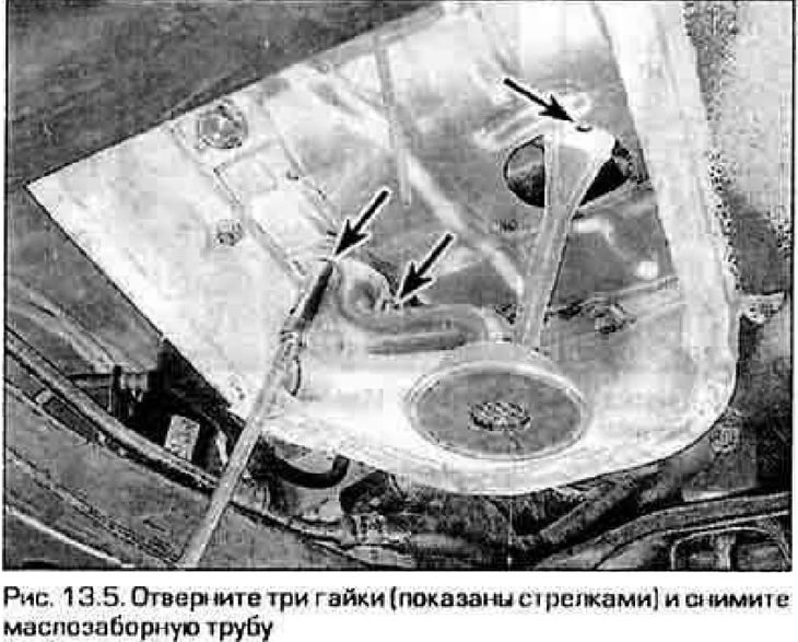
5. Remove the oil pan (see paragraph 12). Remove the oil intake pipe (figure 13.5).

5. Remove the oil pan (see paragraph 12). Remove the oil intake pipe (figure 13.5).


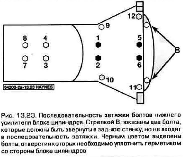
6. Loosen the bolts in the opposite order to that shown in the figure 13.23, unscrew them and remove the lower crankcase reinforcement.

Note: On engines produced since 1998, the bolt pattern on the transmission side is slightly different.


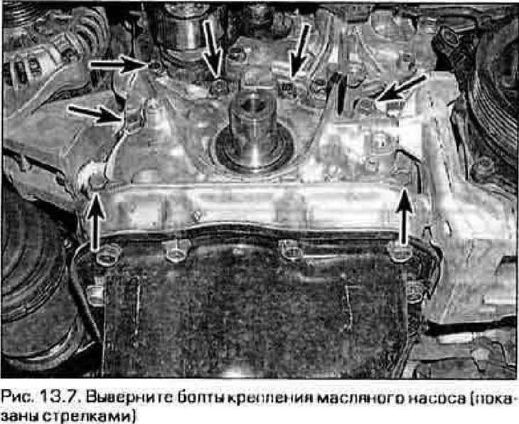
7. Loosen the bolts securing the oil pump to the cylinder block and remove the pump (Fig. 13.7). If necessary, gently pry the pump housing away from the block with a small screwdriver.


7. Loosen the bolts securing the oil pump to the cylinder block and remove the pump (Fig. 13.7). If…


Examination


8. Place the pump on the workbench. Remember to what depth the cuff is pressed into the pump body. Pull the cuff out of the socket (do not damage the bore under the cuff).

9. Remove the screws connecting the cover to the pump body. Remove and inspect the cover for damage or warping.

10. Unscrew the pressure reducing valve. Remember which side the valve parts are inserted into the bore. Remove the pump gears, wash them in solvent and reinstall them.

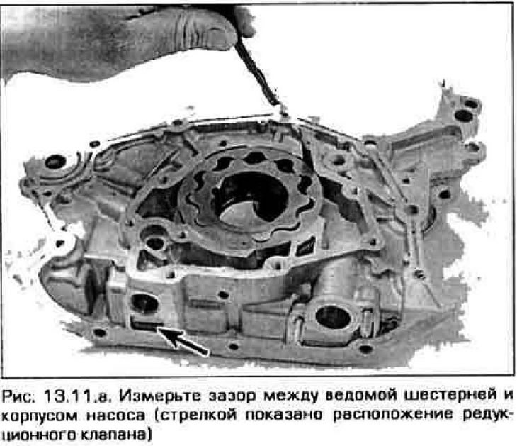
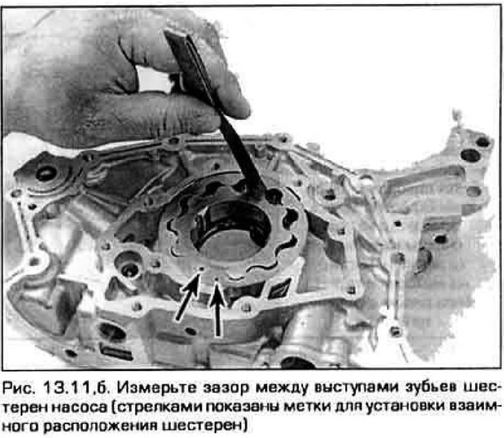
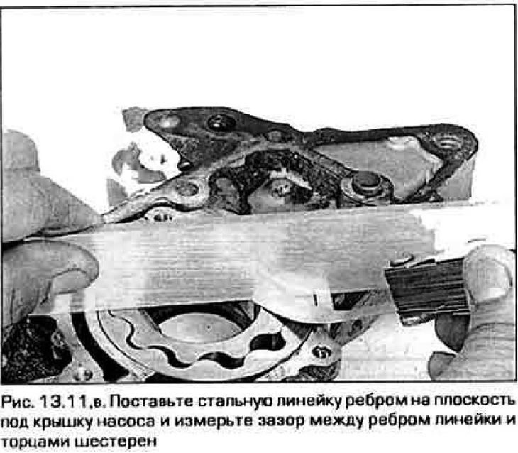
11. Measure the following gaps with feeler gauges and compare them with the values specified in Technical data.
  • a) Between the driven gear and the pump body (figure 13.11,a)
  • b) Between the projections of the teeth of the driving and driven gears (figure 13.11,b)
  • c) Between the ends of the gears and the plane of the cover (figure 13.11,c)

c) Between the ends of the gears and the plane of the cover (figure 13.11,c)


c) Between the ends of the gears and the plane of the cover (figure 13.11,c)


c) Between the ends of the gears and the plane of the cover (figure 13.11,c)


12. Measure the length of the pressure reducing valve spring in its free state. Compare the result with the value specified in Technical data. Replace the spring if necessary.


13. Clean and rinse the pump parts before assembly.

14. Remove the outer surface of the new seal with clean engine oil. Press the cuff into the socket with a hammer through a mandrel with an outer diameter slightly smaller than the outer diameter of the cuff (for this purpose, you can use a piece of pipe or a socket head of a suitable size). Press the cuff to the same depth as before disassembly. Wet the working edge of the cuff with oil, which contacts the nose of the crankshaft.

15. Dip the plunger of the pressure relief valve into oil and assemble the valve. Secure the valve plug with a snap ring.

16. Dip the pump gears in oil and insert them into place.

17. Fill the pump cavities with technical petroleum jelly (this will help the pump start pumping oil immediately after the engine starts).

18. Install the pump cover, apply a compound to the threads of the cover mounting screws to prevent them from loosening. Insert and tighten the screws securely.

19. Inspect the oil intake pipe and filter mesh to ensure they are not clogged with dirt. Flush the pipe and mesh, or replace the entire assembly.

Installation


20. Scrape off any remaining old gasket and sealant from the cylinder block mounting surface. Wash the mating surfaces of the pump and block with nitro solvent or acetone.

21. Apply a thin layer of sealant to the pump mounting surface and place a new gasket on it. Reinstall the pump. If necessary, rotate its gears to engage them with the shaft nose. Be careful when applying the sealant so that it does not get into the pump channels.


22. Screw in the bolts and tighten them to the specified torque.

23. Wipe the lower surface of the cylinder block and the mating surface of the booster. Apply a bead of RTV sealant around the perimeter of the booster mounting surface and around the four booster-to-rear main bearing cap bolt holes. Install the amplifier within 5 minutes after applying the sealant. Gradually, in three to four passes, tighten the amplifier mounting bolts to the required value in the sequence shown in the figure 13.23.

23. Wipe the lower surface of the cylinder block and the mating surface of the booster. Apply a…


24. The rest of the assembly is carried out in the reverse order of disassembly.
This article is available at: russian, bulgarian, belarusian, ukrainian, serbian, croatian, romanian, polish, slovak, hungarian
This text was checked by: German Vorobyov
Share with friends on social networks:

Previous
Capella 6 » 4-cylinder engines
Next

Oil pan — removal and installation
Front Crankshaft Oil Seal — replacement
Cylinder head — removal and installation
Exhaust manifold — removal and installation
Intake manifold — removal and installation
Flywheel (faceplate) — removal and installation
Rear crankshaft oil seal — removal and installation
Powertrain Supports — inspection and replacement
More articles on repairing other Mazda models
Fuel pump — removal and installation Mazda Familia 5 (1985-1989)
Oil pump — description Mazda3 BK (2003-2009)
Oil pump — general information Mazda6 GG (2002-2008)
Removal and installation the water pump Mazda CX-5KE (2012-2017)
Removal and installation a vacuum pump Mazda 121 (3) (1996-2003)
Link in different formats to this article
Comments and feedback from visitors
No comments yet


How much will 43 + 36 ?


Capella 6 (1997-2005, petrol) 
  • General information
  • Introduction to guide
  • User manual
  • Troubleshooting
  • Maintenance
  • Power unit
  • 4-cylinder engines
  • 6-cylinder engines
  • Engine overhaul
  • Cooling and ventilation
  • Power and exhaust systems
  • Engine electrics
  • Control system
  • Transmission
  • Mechanical gearbox
  • Automatic gearbox
  • Clutch and drive shafts
  • Chassis
  • Brake system
  • Car suspension
  • Steering
  • Body
  • Exterior (external elements)
  • Interior (internal elements)
  • Doors, windows and locks
  • Electrical equipment
  • Equipment and devices
  • Electrical circuits
Capella 5 (1991-1997) 
  • General information
  • User manual
  • Maintenance
  • Helpful hints
  • Power unit
  • Petrol engines 1.6 and 1.8
  • Petrol engines 2.0
  • 2.5 petrol engines
  • Overhaul engines 1.6 and 1.8
  • Overhaul engines 2.0 and 2.5
  • Diesel engine 2.0
  • Engine electrics
  • Cooling system
  • Air conditioner
  • Carburetor Nikki 30/34
  • Power system (1.6 and 1.8)
  • Power system (2.0 and 2.5)
  • Control system
  • Transmission
  • Mechanical gearbox
  • Automatic gearbox
  • Clutch and axles
  • Chassis
  • Brake system
  • Suspension and wheels
  • Steering
  • Body
  • Exterior (external elements)
  • Interior (internal elements)
  • Doors and windows
  • Electrical equipment
  • Equipment and devices
  • Electrical circuits
Capella 4 (1987-1992) 
  • General information
  • Introduction to manual
  • Vehicle specifications
  • Power unit
  • Engine repair
  • Lubrication system
  • Cooling system
  • Fuel system (carburetor)
  • Fuel injection (FE)
  • Fuel injection (DOHC)
  • Fuel system (diesel)
  • Ignition system
  • Transmission
  • Clutch
  • Gearbox
  • Drive shafts
  • Chassis
  • Front suspension
  • Rear suspension
  • Steering system
  • Brake system
  • Electrical equipment
  • Equipment and devices
  • Electrical circuits
Capella 3 and 4 (1982-1992) 
  • General information
  • User manual
  • Maintenance
  • Power unit
  • Gasoline engine
  • Engine overhaul (gasoline)
  • Diesel engine
  • Cooling and heating
  • Supply system
  • Ignition system
  • Emission reduction
  • Transmission
  • Clutch
  • Mechanical gearbox
  • Automatic gearbox
  • Drive shafts
  • Chassis
  • Brake system
  • Suspension and wheels
  • Steering
  • Body
  • Exterior (external elements)
  • Interior (internal elements)
  • Electrical equipment
  • Equipment and devices
  • Power devices
  • Electrical circuits
Capella 3 (1982-1992, petrol) 
  • General information
  • User manual
  • Maintenance
  • Troubleshooting
  • Late models
  • Power unit
  • Engine in car
  • Engine overhaul
  • Cooling and heating system
  • Fuel and exhaust system
  • Engine electrical system
  • Emission control system
  • Transmission
  • Mechanical gearbox
  • Automatic gearbox
  • Clutch and drive shafts
  • Chassis
  • Brake system
  • Suspension and wheels
  • Steering
  • Body
  • Exterior (external elements)
  • Interior (internal elements)
  • Electrical equipment
  • Equipment and devices
  • Lighting and lamps
  • Electrical circuits
MazBook.ru © 2018–2026 · Mobile version · Articles and news · Sitemap: EN BG BY UA RS HR RO PL SK HU · Feedback · Site search · Add to bookmarks Familia 5 (BF) · Familia 6 (BG) · Capella 3 (GC) · Capella 3 and 4 (GC) · Capella 4 (GD) · Capella 5 (GE) · Capella 6 (GF) · Mazda3 BK · Mazda6 GG · CX-5KE · Mazda 121 (3) · Mazda BT-50 (1) ·
By continuing to use the site, you agree to the use of cookies 🔐