


Removal
1. Disconnect the negative cable from the battery.
Caution: If your vehicle has a theft-protected audio system, make sure you have the unlock code before disconnecting the battery.
2. Remove the cylinder head cover (see paragraph 4).
3. Remove the spark plugs from the cylinders (see chapter 1).
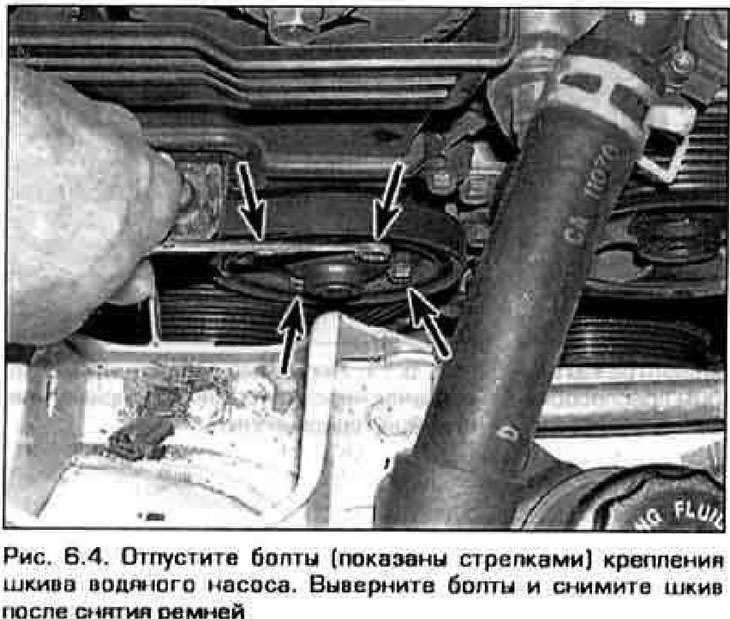
4. Loosen the water pump pulley mounting bolts (Fig. 6 4). Remove the power steering pump, compressor and generator drive belts (see chapter 1). Remove the water pump pulley.
5. Place chocks under the rear wheels and apply the parking brake. Raise the front of the car and support it on stands.
6. Remove the front right wheel.
7. Remove the right front mudguard.
8. Remove the crankshaft pulley (see paragraph 11).
9. Support the engine from underneath with a jack stand. Place a wooden block on the jack stand to prevent denting the engine sump. Raise the trolley to support the weight of the power unit and remove the left engine mount (see paragraph 16).
Caution: The engine must be supported throughout the operation. Make sure the lifting equipment is secure.
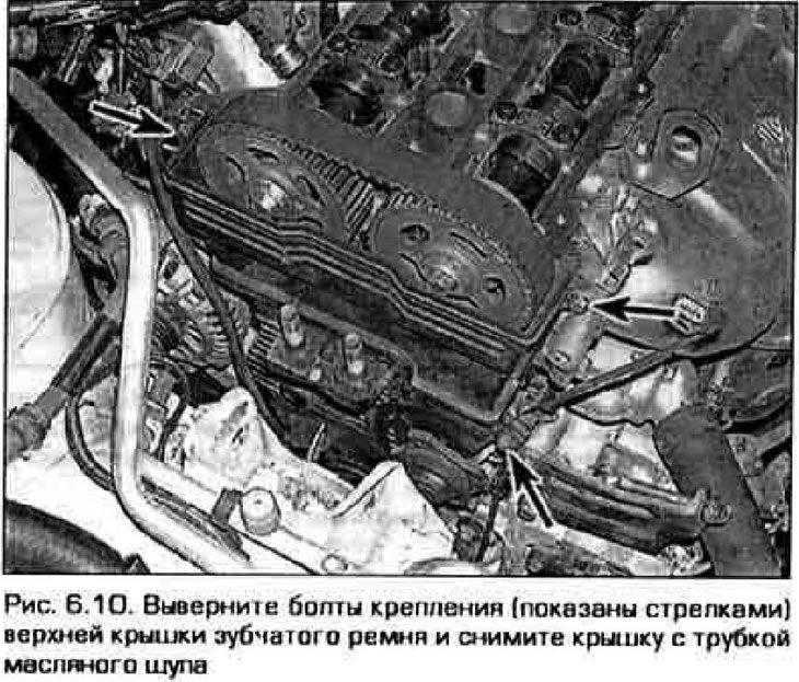
10. Unscrew the bolts securing the upper timing belt cover and remove the cover with the dipstick tube (Fig. 6.10).
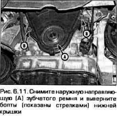
11. Remove the lower timing belt cover (figure 6.11).
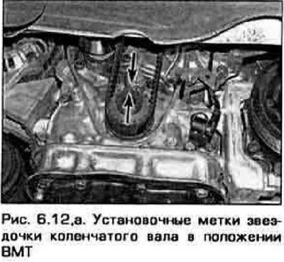
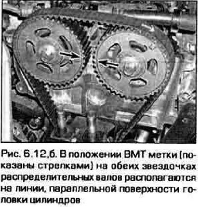
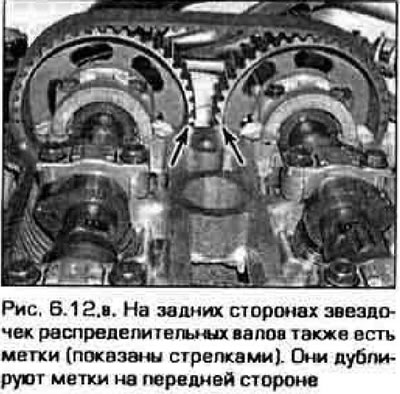
12. Temporarily tighten the crankshaft pulley bolt and turn the crankshaft until the timing marks on the crankshaft and camshaft sprockets are aligned (fig. 6.12, a-c).
 |
 |
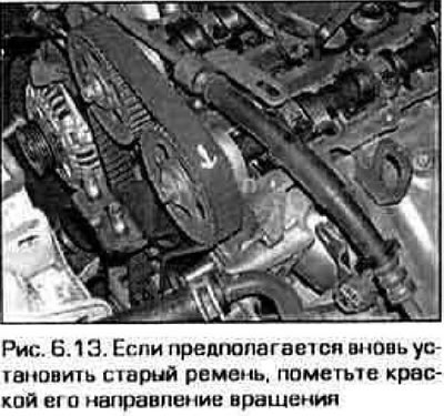
13. If you intend to continue using the old belt, mark it relative to the sprockets and put an arrow on it showing the direction of rotation (figure 6.13).
Data provided by the website: www.MazBook.ru
14. There is a special device. which is inserted between the camshaft sprockets and prevents them from rotating. This device makes the procedure easier because it prevents the camshafts from turning under the action of the valve springs.
Note: This job can be done without the specified tool, but you will experience some inconvenience when installing the belt, since you will need to slightly turn the sprockets until the marks align and hold them in this position until the belt is put on. It is difficult to do this alone.
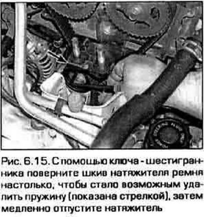
15. Release the belt tension (figure 6.15).
16. Remove the timing belt.
17. If necessary, you can remove the crankshaft sprocket by pressing it away from the engine crankcase with two pry bars or strong screwdrivers. Before removing the sprocket, remove the crankshaft position sensor.
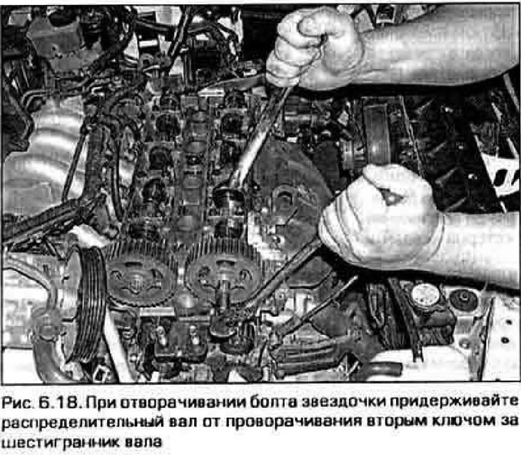
18. If necessary, you can remove the sprockets from the camshafts. When unscrewing the bolts securing the sprockets, hold the camshaft from turning with a second key on the hexagon on the shaft (figure 6.19). The sprockets on the front surface have marks: "I" for the intake shaft and "E" for the exhaust shaft.
Inspection
Warning! Do not bend, twist, or invert the belt. Do not allow it to come into contact with oil, fuel or coolant. Do not use belt tension to prevent the crankshaft or camshafts from turning when tightening the sprocket mounting bolts. When the belt is removed, do not turn the crankshaft and camshafts more than a few degrees (for alignment of marks only).
19. Check the tensioner pulley and idler roller bearings for binding during rotation and excessive play. Inspect the tensioner spring for damage. Replace faulty parts if necessary.
20. If the belt is severely damaged or breaks while the engine is running, before installing a new one, find out and eliminate the cause of the damage to the old belt. This could be due to damaged sprocket teeth, dirt or foreign objects stuck in the tooth cavities, or a defect in the belt itself. In any case, carefully inspect the teeth of all sprockets and clean their gullies.
21. If the old belt has torn or broken teeth (figure 6.21), it is possible that this is the result of a jammed water or oil pump, or camshaft.
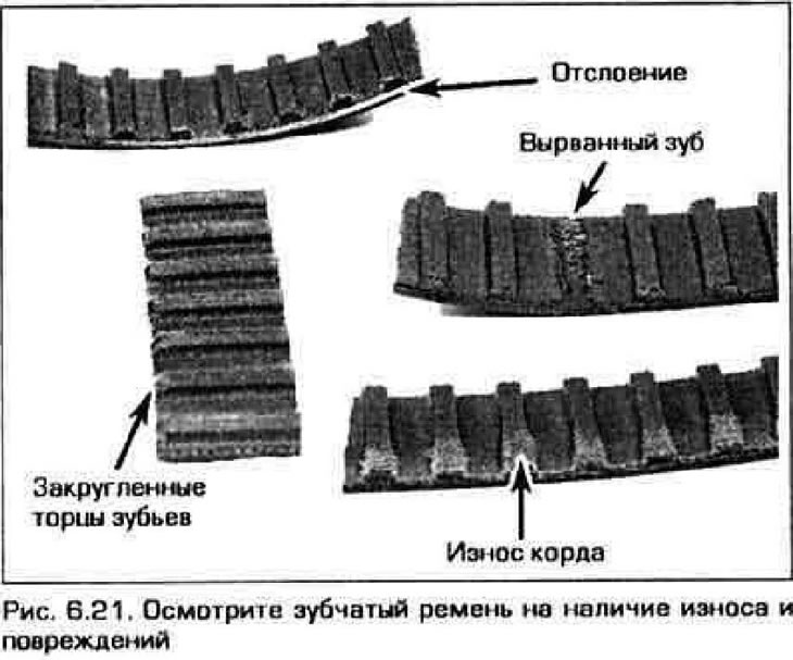
22. If the belt has cracks or noticeable wear, check for nicks or burrs on the sprocket teeth.
23. If wear or damage is observed on only one side of the belt, check the guide, pulleys and belt sprockets for distortion. Also check the oil seals on the front of the engine and replace them if necessary.
24. Replace the belt if there is visible damage or if you have even the slightest doubt about its condition. Before installing a new belt, eliminate all causes that could lead to its damage. Note: It is recommended to replace the belt every time it is removed, regardless of the cause, as a belt break while the engine is running will result in very expensive repairs.
Installation
25. Clean the front side of the engine in the belt area from dirt and oil traces.
26. If the tensioner pulleys and idler roller were removed, reinstall them.
27. If the belt sprockets were crushed, reinstall them. The crankshaft sprocket key must be directed with the narrow side towards the oil pump housing. Tighten the sprocket mounting bolts to the torque specified in Technical data.
28. Align the marks on the crankshaft and camshaft sprockets (see figure 6 12.a-c). The pointer on the crankshaft sprocket must align with the mark above the pulley. The "I" and "E" marks on the camshaft sprockets must align with the horizontal surface of the cylinder head.
Note: If necessary, turn the camshafts slightly to correctly align the marks.
29. Place the belt on the crankshaft sprocket and engage the belt teeth with the teeth of the camshaft sprockets as follows. so that all the slack in the belt falls on the tensioner branch. If the belt is not being replaced, install the old belt according to the marks and arrows made during removal. If a camshaft sprocket locking device was used during disassembly, remove it.
30. Turn the tensioner roller so that its spring can be inserted (see item 15).
31. Turn the crankshaft two full revolutions and check the alignment of the timing marks on the crankshaft and camshaft sprockets (see figure 6 12,a-c).
Caution: If you feel any additional resistance while turning the crankshaft, stop turning it immediately. It is possible that due to incorrect valve timing, the valve hit the piston. Check again that the crankshaft and camshaft sprockets are installed correctly.
32. The remaining parts were crushed during disassembly. install them in reverse order. Start the engine and make sure it is running properly.
Caution! Do not start the engine unless you are 100% sure that the timing belt is installed correctly. Incorrect belt installation will result in long and expensive engine repairs.