
Removing
1. Remove the cylinder head cover (see paragraph 4).
2. On models of early releases before 1997, remove the ignition distributor (see chapter 5).
3. Remove the timing belt and camshaft sprockets (see paragraph 6).
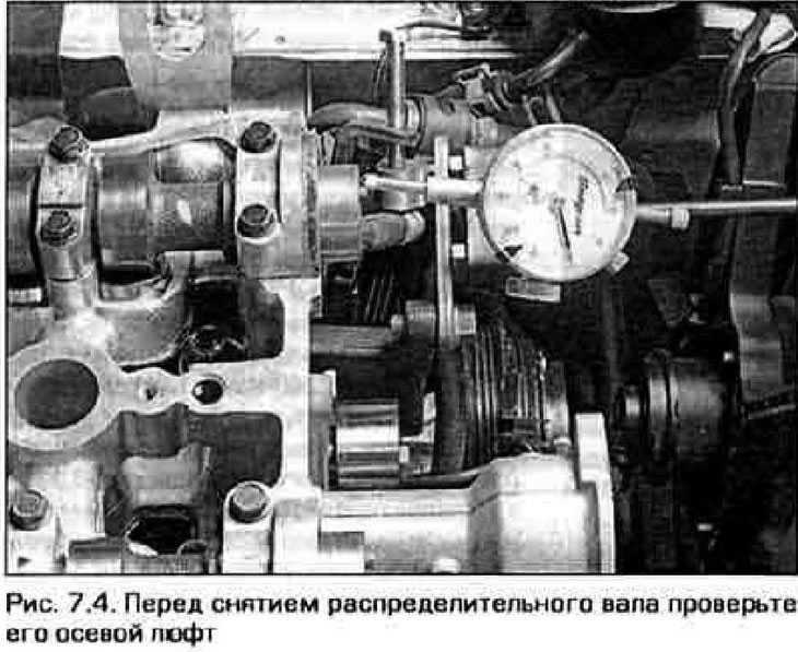
4. Measure the axial play of the camshafts with a dial indicator (fig 7.4). If the backlash exceeds the allowable value (see technical data), replace the shaft and/or shaft thrust flange.
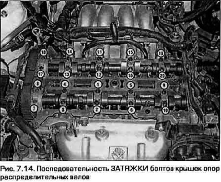
5. In the sequence opposite to that shown in fig. 7 14, loosen the camshaft bearing cap bolts 1/4 turn at a time, one at a time, until you can remove them by hand.
Be careful: when equipping the bolt tightening, the camshaft must rise evenly. If one of the ends of the shaft stops rising and the shaft is warped, re-tighten the support cap bolts, rotate the camshafts and start releasing them again. DO NOT attempt to lift the camshaft with a lever or other force.
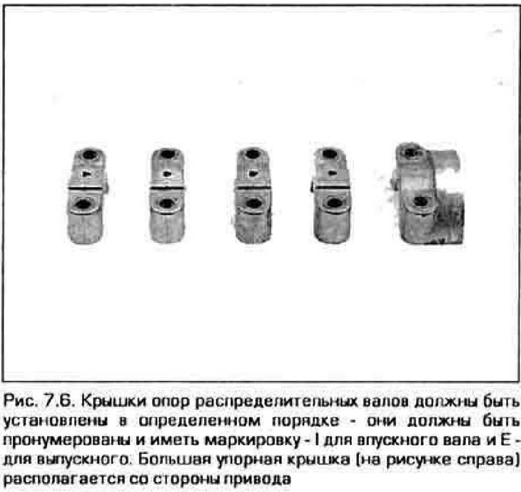
6. Finally turn out all bolts and remove covers of support. Store them in a sequence that will allow them to be reinstalled in their original locations. In addition, lids must be labeled (pic. 7.6).
7. Raise the camshaft without distortion and remove it from the engine.
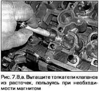
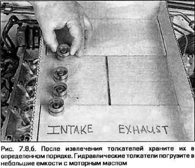
8. Pre-1997 engines use hydraulic tappets, while later engines use shim tappets. Regardless of the type of pushers, they can be removed using a magnet (fig 7.8,a). Store pushrods with their gaskets so that when reassembling, all parts can be installed in their original places (pic. 7.8b). Keep in mind: hydraulic tappets should be stored in clean engine oil "upside down".
 |  |
9. Thoroughly wipe the camshafts, remove the cuffs from them and proceed to inspect the shafts and pushers (see chapter 2B).
Installation
10. Lubricate the pushers with molybdenum grease and insert them into their original places. Install adjusting shims on the upper ends of the pushers (on engines manufactured since 1998).
11. Lubricate the cams and journals of the camshaft bearings with molybdenum grease.
12. Carefully lower the shaft onto the supports. Rotate the shaft so that the forces from the valve springs are approximately equal along the length of the shaft. Install the support covers in the correct order and screw in the bolts of their fastening only by hand so far.
13. Before installing the front (stubborn) Apply a light coat of RTV Sealant to the outer edge of the base that mates with the cylinder head. Keep in mind the cover must be replaced immediately after applying the sealant, otherwise the sealant will dry instantly.
14. In the sequence shown in fig. 7.14, gradually tighten the camshaft cap bolts no more than 1/4 turn at a time until the required torque is reached, which is indicated in Technical data.
15. Lubricate a new cuff with engine oil and put it on the shaft by hand.
16. Using a piece of pipe or an end head of suitable diameter, press the collar flush with the shaft cover torsion or to the depth of the previously installed collar.
17. Establish remaining details in sequence, opposite to their removal.
18. Start the engine and check there. that it works fine.
Notes. On some models, after assembly, the valve lifters may make noise. If the pushers are found to be serviceable after the inspection described in chapter 2B, then the cause of the noise may be a malfunction of the oil pump. Due to leaks in the pump, air can enter the oil, although there are no oil leaks from the outside. Air entering the pushers displaces oil from it and causes a rumble. If the noise persists after the engine warms up, the oil pump may need to be replaced.