


Contents: Removal ⇓ Installation ⇓
Removal
1. Relieve the pressure in the fuel system (see chapter 4). Disconnect the negative cable from the battery.
Warning; If your vehicle's audio system is equipped with an anti-theft device, make sure you have the unlock code before disconnecting the battery.
2. Remove the air intake duct and air cleaner (see chapter 4).
3. Remove the starter (see chapter 5).
4. Disconnect all electrical connectors and ground straps from the transmission. Disconnect the wiring harness from the transmission.
5. Shift the gearbox into reverse.
6. Disconnect the gear shift rod and torque rod from the transmission (see paragraph 2). It is not necessary to disconnect the rods from the gear shift lever housing. Move the rods to the side and tie them from below to the body with a piece of wire.
7. Disconnect the vehicle speed sensor connector (see chapter 6).
8. Remove the clutch slave cylinder from the transmission and tie it up somewhere to the side.
Be careful: Do not kink the clutch line and DO NOT DEPRESS the clutch pedal while the slave cylinder is removed.
9. Raise the vehicle and support it on stands. Secure the engine to the cross member (see Figure 8.9 in Chapter 7B). If there is no such device, tighten the engine with a hoist.
10. Remove the upper transmission-to-engine mounting bolts.
11. Remove the fuel filter (see chapter 1).
12. Remove the left engine mount (see Chapter 2A).
13. Remove the front wheels of the car.
14. Drain the transmission oil (see chapter 1).
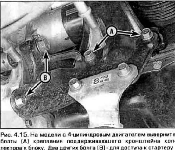
15. On a 4-cylinder model, remove the intake manifold support bracket (figure 4.15).
16. Remove the exhaust system.
17. Disconnect the steering rods from the steering knuckles (see chapter 10).
18. Remove the drive shafts and intermediate shaft (see chapter 8).
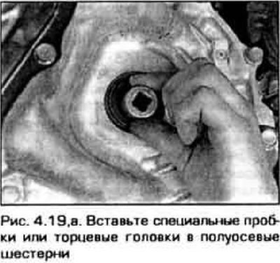
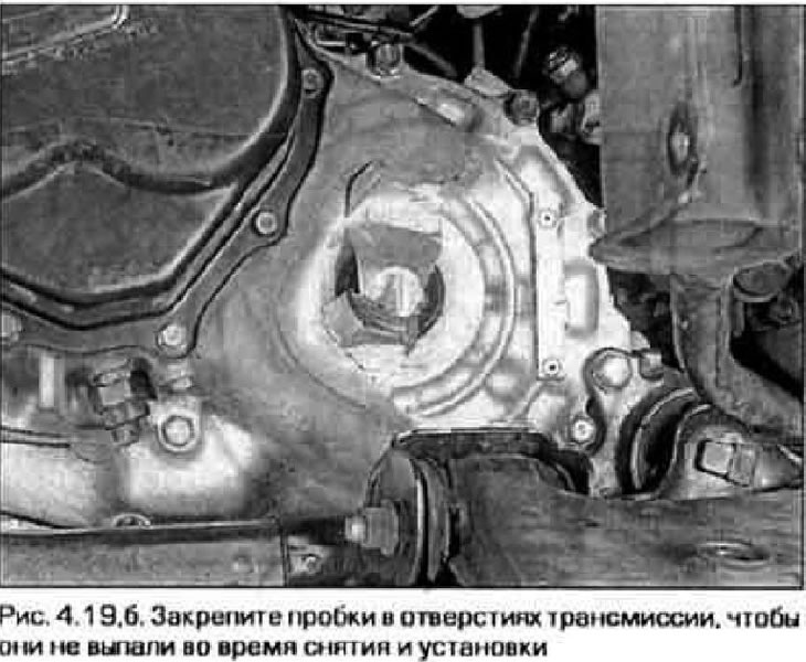
19. Secure the differential axle gears from shifting. There are special plugs for this, but if you don't have any, you can get by with socket heads of the appropriate size (figure 4.19,a,6) or wooden plugs. Please take note. If the axle gears are not secured and become displaced, the transmission will have to be disassembled.
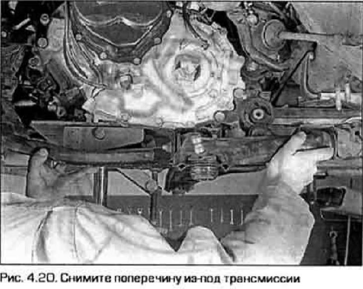
20. Remove the mud flaps. Unscrew the six bolts securing the crossmember to the transmission floor and remove the crossmember (figure 4.20, see also Figure 1.1).
21. On vehicles with ABS, disconnect the wheel speed sensor wiring on both sides of the vehicle.
22. Mark the position of the transmission support beam relative to the underbody.
23. Unscrew the bolts and nuts securing the support beam. Photos of the support beam are shown in chapter 7B.
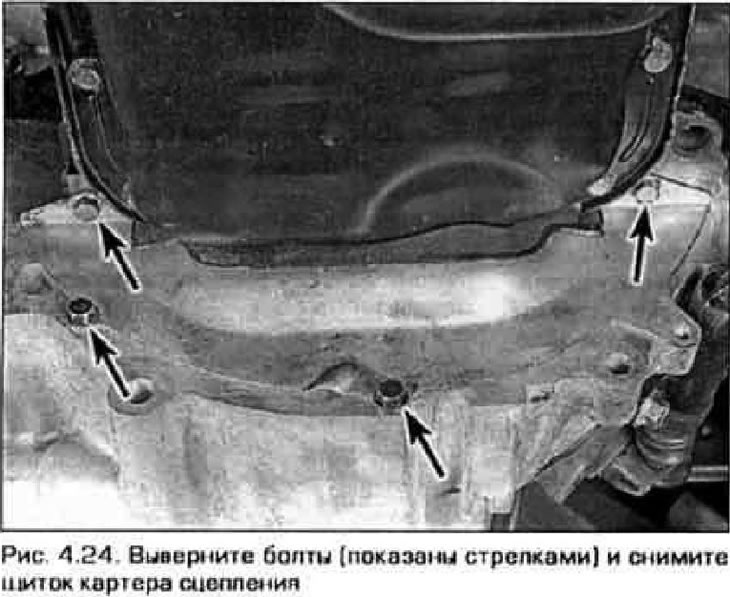
24. Remove the shield that covers access to the clutch (figure 4.24).
25. Support the transmission from below with a jack dolly. Securely secure the transmission on the dolly platform with a chain.
26. Remove the transmission coupler and support bracket. For more information on power unit supports, refer to the chapters 2A or 2B.
Based on website data (mazbook.ru)
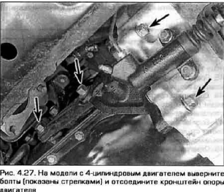
27. Remove the transmission support bolts above the intermediate shaft and the bolt next to the clutch slave cylinder (figure 4.27). Remove the two rear engine mount bracket bolts.
28. Inspect the transmission again to ensure all hoses and wires are disconnected and that nothing will interfere with its removal. Separate the transmission from the engine. Once the input shaft is free, lower the jack with the transmission and roll the transmission out from under the vehicle.
29. After removing the transmission, all clutch components become accessible for inspection. It is recommended to make it a rule to change the clutch parts (primarily the driven disk and release bearing, see chapter 8) if the transmission is removed for some reason.
Installation
30. Install the clutch (if it was removed).
31. Secure the transmission to the jack dolly, roll it to the installation location and lift it into the installation position. Slide the transmission toward the engine, aligning the dowel pins with the corresponding holes and the input shaft with the clutch disc hub. Do not apply excessive force to the transmission - if the input shaft does not enter the disc hub freely, change the angle of the transmission relative to the engine or rotate the input shaft of the transmission so that its splines align with the splines of the friction disc.
32. Install the lower transmission to engine mounting bolts and the rear engine support bracket bolts. The installation of the supports is described in detail in chapter 2A.
33. Install the lower left support onto the transmission (tightening torques are given in chapter 2A).
34. Connect the gear shift rod and torque rod to the transmission.
35. Install the support beam under the transmission, aligning the previously applied marks and tighten the bolts of its fastening to the required torque (see Figure 8.23 in Chapter 7B). Secure the power steering hydraulic line.
36. Remove the plugs from the transmission axle gears.
37. Install the intermediate shaft drive shafts (see chapter 8).
38. Install the crossmember under the transmission and tighten its bolts to the specified torque.
39. Connect the steering rods to the steering knuckles (see chapter 10).
40. Install the mudguard and front wheels. Lower the car to the ground.
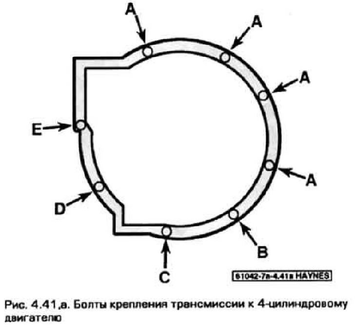
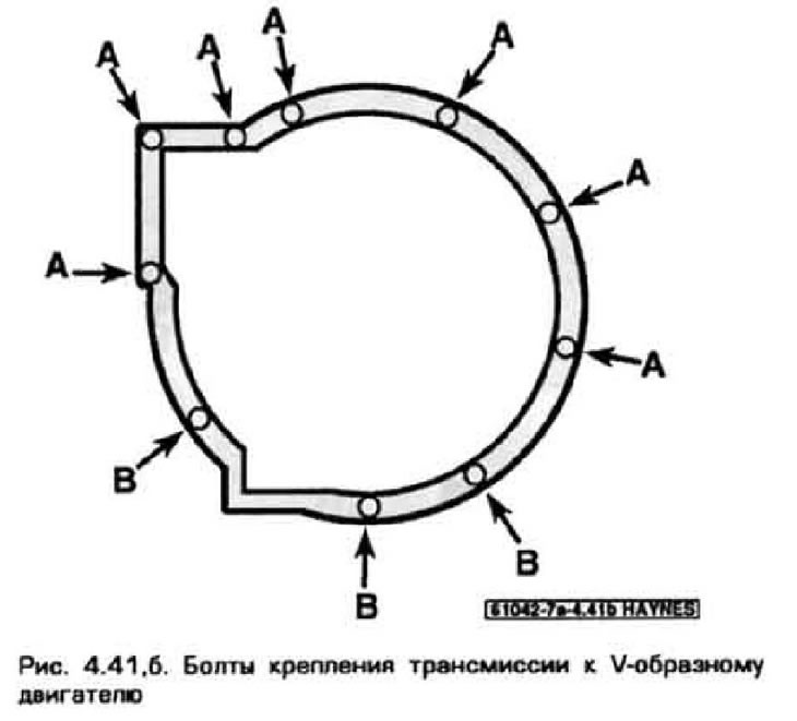
41. Screw in the remaining transmission mounting bolts (figure 4.41, a, b) and tighten them to the required torque.
42. Screw in the front engine mount mounting bolts (see Chapter 2A).
43. The remaining parts are installed in the reverse order of their removal.
44. Fill the transmission with oil (see chapter 1).
45. Check the operation of the clutch and bleed air from its hydraulic drive.
46. Take a test drive to check the operation of all systems. Check for leaks.
47. If vibration of the power unit is observed, loosen and re-tighten the support bolts to the required torque.
48. Adjust the wheel alignment angles.