
Examination
1. When checking, the engine should be slightly raised to remove the load from its supports.
2. Raise the vehicle and place it on jack stands. Place a hydraulic jack under the engine, placing a wooden block on its head so as not to damage the sump. Carefully jack up the engine just enough to relieve the mounts.
Attention! DO NOT work under the engine if it is only on a jack.
3. Inspect the engine mounts. First of all, pay attention to the rubber blocks - are there any cracks in them, delamination from the metal base, whether the rubber has hardened. The destruction of the rubber block usually does not chime from the center hole.
4. Check for play in the supports. To do this, insert a strong screwdriver or pry bar into the support and shake the engine relative to the support. If play is evident, lower the engine and tighten the support hardware.
5. To reduce the likelihood of rubber degradation, the supports should be coated with a protective compound.
6. Disconnect the negative cable from the battery, set the parking brake, put blocks under the wheels, raise the front of the car and support it on props (if it hasn't already been done).
Warning. If your vehicle has an anti-theft audio system, make sure you have the unlock code before disconnecting the battery.
Replacement
Right support (passenger side)
7. The support supporting the power block from the side of the timing mechanism drive is attached to the block and to the bracket. mounted on the chassis. To replace the support, unload it by supporting the engine from below with a hydraulic jack. Place a piece of wood on top of the jack head to protect the pallet. Do not place a jack under the sump drain plug.
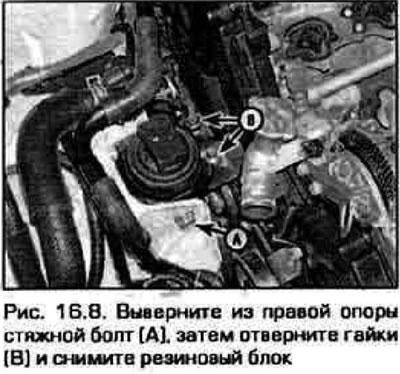
8. Turn away a coupling bolt of a support, then bolts of fastening of a support to the engine and pull out the rubber block (pic. 16.8).
9. Installation of the support is carried out in reverse order.
Note. Before final tightening of the fasteners, lower the power block and remove the supporting jack. If several supports have been replaced, see below for final tightening procedures.
Front support
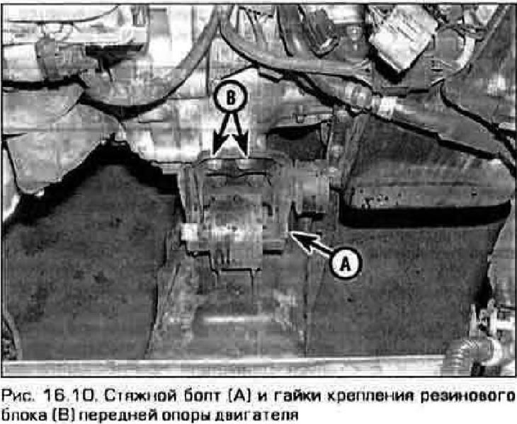
10. The front support is located between the engine and the radiator, in the connection of the engine with the transmission (pic. 16 10).
Application. If you only have to replace the front or rear support, then it is easier to remove the entire subframe than to raise the power block just enough to get rid of the studs (see chapter 7).
11. To crush the front support, follow the steps indicated in paragraphs. 7-9.
12. Installation is performed 0 in reverse order.
Note. Before final tightening of the fasteners, lower the power block and remove the supporting jack. If several supports have been replaced, see below for final tightening procedures.
Rear support
13. If you do not remove the intake manifold, access to this support will be difficult and only possible from below. Loosen the pinch bolt and lift the power block to take the load off the support.
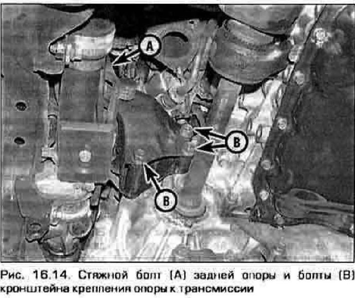
14. Unscrew the bolts securing the support to the transmission, unscrew to the end and pull out the tie bolt, then raise the power unit so that it is possible to pull out the spore (pic. 16.14).
15. Installation is carried out in reverse order.
Note. Before final tightening of the fasteners, lower the power block onto the supports and remove the supporting jack. If several supports have been replaced, see below for final tightening procedures.
Left support (from the driver's side)
Upper support
16. The support on the driver's side is attached from above to the transmission and to the chassis (fig 16.16). To access the support, remove the inlet duct and air cleaner (see chapter 4).
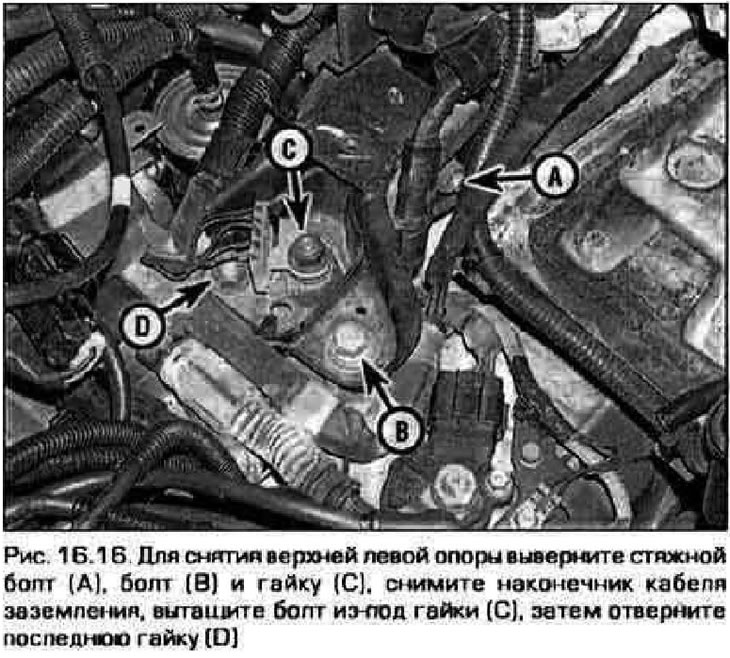
17. Support the power block, turn out the coupling bolt, bolt and nut securing the support to the transmission and remove the spore.
18. Install the spore in reverse order.
Note. Before final tightening of the fasteners, lower the power block and remove the supporting jack. If several supports have been replaced, see below for final tightening procedures.
Bottom support
19. On most models there is another support under the junction of the engine with the transmission (pic. 16.19).
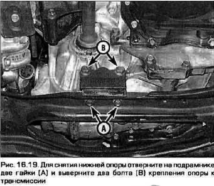
20. Support the power block. Remove the two bolts securing the support to the transmission and the two nuts securing the subframe.
21. Install the support in reverse order.
Note. Before final tightening of the fasteners, lower the power block and remove the supporting jack. If several supports have been replaced, see below for final tightening procedures.
Final tightening of all supports
22. When all supports are finally tightened, the vehicle must be level and the weight of the power unit must be on the supports. Fill threaded connections with anti-self-loosening compound. Screw in all fasteners of all supports, first by hand, then gradually tighten it until the required torque is reached.