
Removing
1. Remove cylinder head covers (see paragraph 4), toothed belt and camshaft sprockets (paragraph 6). If you intend to remove the front block camshafts, on 1997 and earlier models, also remove the ignition distributor (see chapter 5). To work with the shafts of the rear block, remove the intake manifold (see paragraph 8).
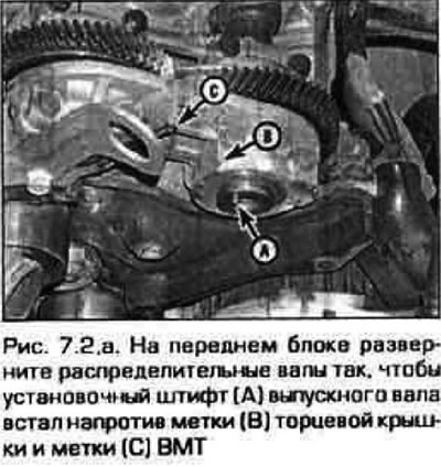
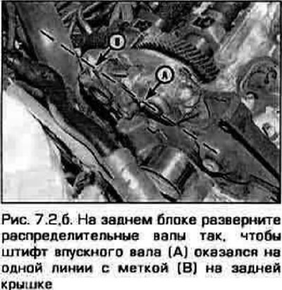
2. When removing the camshafts, be careful. The bolts of the support covers must be loosened strictly in the specified sequence. Otherwise, the pressure of the riveted springs will not be balanced along the length of the shaft and the shaft may warp and damage the bearings. In this case, you will have to change the cylinder head. To equalize the pressure of the springs on the cams, rotate the shafts as shown in fig. 7.2, a, b.
 |  |
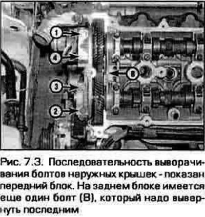
3. Gradually. Loosen the outer cover bolts one by one, no more than 1/4 turn at a time in sequence. shown in Fig. 7.3.
4. Remove the cuff and cover plug from the front end of the driven shaft.
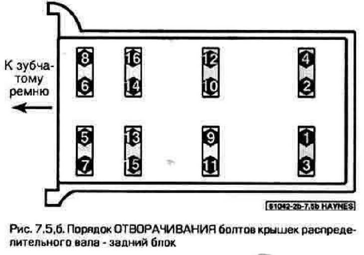
5. Loosen the cover bolts in the sequence shown in fig. 7.5.a, b, 1/4 turn at a time, until it becomes possible to turn them out by hand.

6. Remove the covers and carefully pull the shafts out of the supports. Keep the shafts horizontal.
7. Repeat this operation on the remaining block.
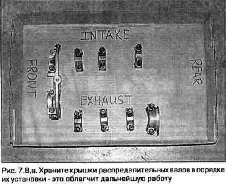
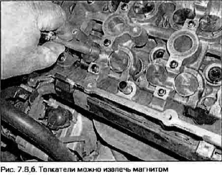
8. Store covers in the order in which they were installed. The covers of the front block are letter-coded, and those of the rear block are number-coded (Fig. 7.8, a). If necessary, remove the pushers with a magnet (with gaskets on engines manufactured since 1999) (pic. 7.8,b). Also store pushers with gaskets in the order they were installed so that they take their original place when frilling. Hydraulic pushers (release models before 1997) store in an oil bath "upside down".
Inspection
9. Inspect the camshafts, tappets and related parts as indicated in chapter 2B. Technical data for camshafts and tappets are also given in chapter 2B.
Installation
10. Lubricate the tappets with molybdenum grease and insert them into the bores in their original positions. If there were shims on the pushers, insert them also into their original places.
11. Lubricate with molybdenum grease the cams and necks of the camshafts, as well as the thrust surfaces of their gears.
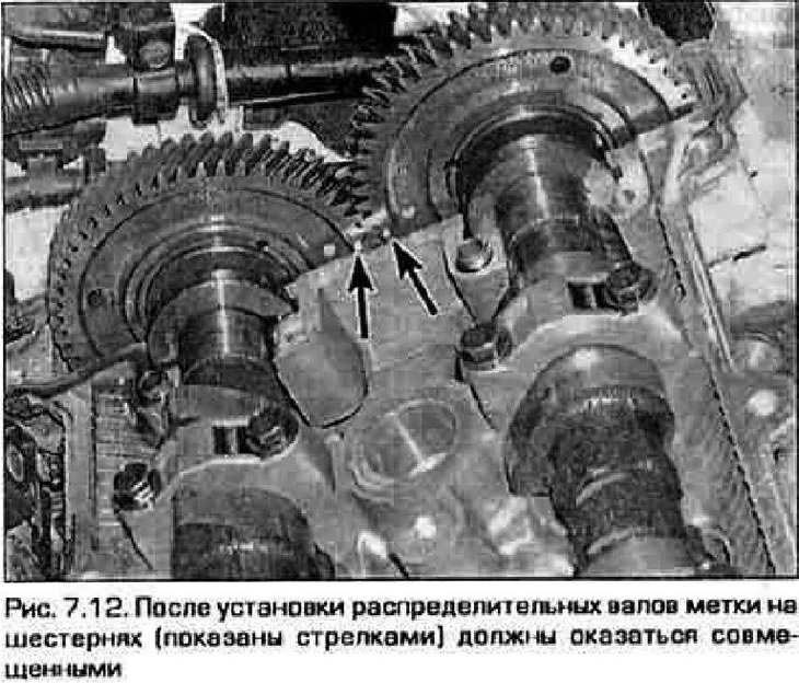
12. Lay the camshafts in the supports and engage their gears so that the alignment marks on the inner sides of the gears are aligned (pic. 7.12).
13. Apply a thin layer of RTV sealant to the outer edges of the cylinder head surfaces under the extreme (stubborn) camshaft bearing caps. Be careful not to let sealant get on the shaft journals.
14. Check shaft alignment (see figure 7.2, a, b). Install the thrust flanges on the caps behind the shaft gears. Tighten the bolts just until the cover is seated in place.
15. Install the remaining covers in their original places.
Note. The shaft covers of the front block are letter marked, and the rear block are numbered.
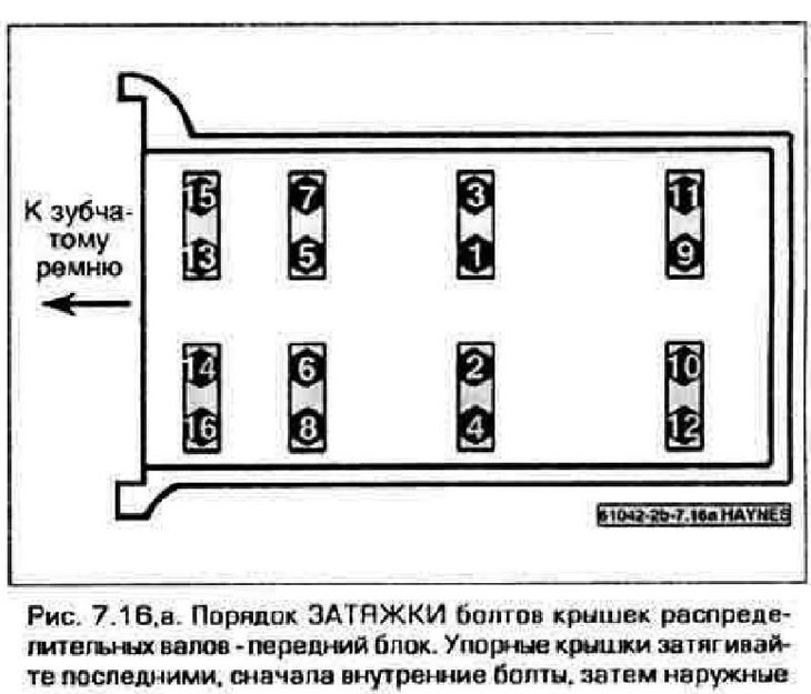
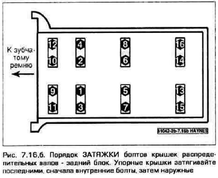
16. Tighten the cap bolts in five or six passes (1/4 turn at a time) until the required effort is reached. Tighten bolts in the recommended sequence (pic. 7.16, a, b).
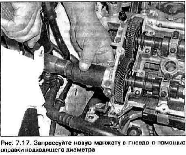
17. Moisten the lip of the shaft seal with clean engine oil. Insert the cuff into the socket and press it through the mandrel slightly smaller than the outer diameter of the cuff (pic. 7.17). After pressing in, the cuff should protrude from the socket by about 5 mm.
18. Insert the plugs into the ends of the extreme supports of the driven shafts. Apply RTV Sealant to the plugs before installing them. Press the plugs with a mallet flush with the supports.
19. Establish the remained details in sequence, return to their removal.
20. On models of release since 1998 check up and, if necessary, adjust backlashes of valves.
21. Start the engine and check its operation.