
Removing
1. Disconnect the negative cable from the battery.
Warning. If your vehicle has an anti-theft audio system, make sure you have the unlock code before disconnecting the battery.
2. Loosen the water pump pulley bolts, then remove the alternator and power steering pump drive belt (see chapter 1).
3. Set piston No. 1 to the TDC position of the end of the compression stroke (see paragraph 3).
4. Loosen the front right wheel nuts, but do not remove them yet.
5. Chock the rear wheels and apply the parking brake. Raise the front of the car and place it on jack stands. Remove the front right wheel.
6. Remove the right front locker.
7. Support the engine from below with a jack. Place a piece of wood on top of the cart to prevent denting the engine pan. Raise the cart to bear the weight of the power unit and remove the left engine mount (see paragraph 16).
Caution: The engine must be supported throughout the entire operation. Make sure the lifting equipment is secure.
8. Remove spark plugs from cylinders (see chapter 1).
9. Turn out two bolts of fastening krone* matte tensioner (pic. 6.9) and remove the tensioner.

10. Disconnect the following electrical connectors on the toothed belt side: crankshaft position sensor, engine temperature indicator sensor, and two coolant temperature sensor connectors. Label the connectors for easy assembly and set them aside.
11. Remove the crankshaft pulley (see paragraph 11).
12. Remove the power steering pump pulley (see chapter 10).
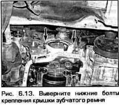
13. From under the car, unscrew the bolts securing the toothed belt cover (pic. 6.13).
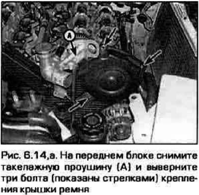
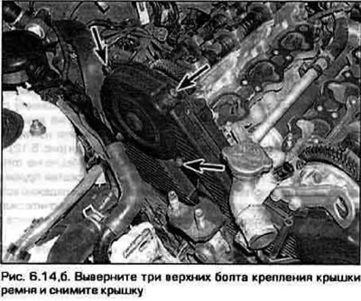
14. Turn out other bolts of fastening of covers of a belt and remove covers and linings from the engine (pic. 6.14, a, b). Remove the oil dipstick tube from the engine.
 |  |
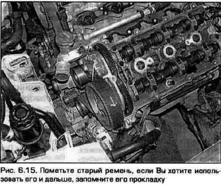
15. See if there are alignment marks on the belt - if you are going to reinstall the old belt, and the marks have worn off, apply them yourself (pic. 6.15).
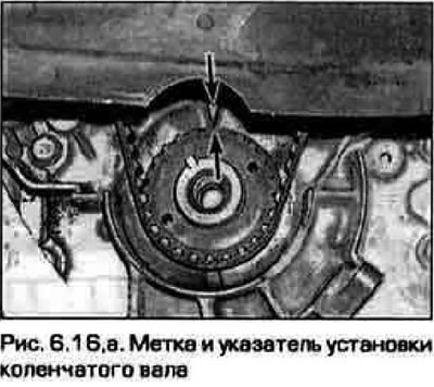
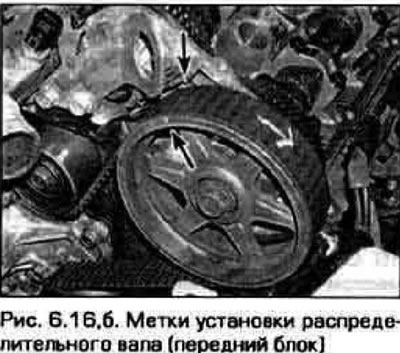
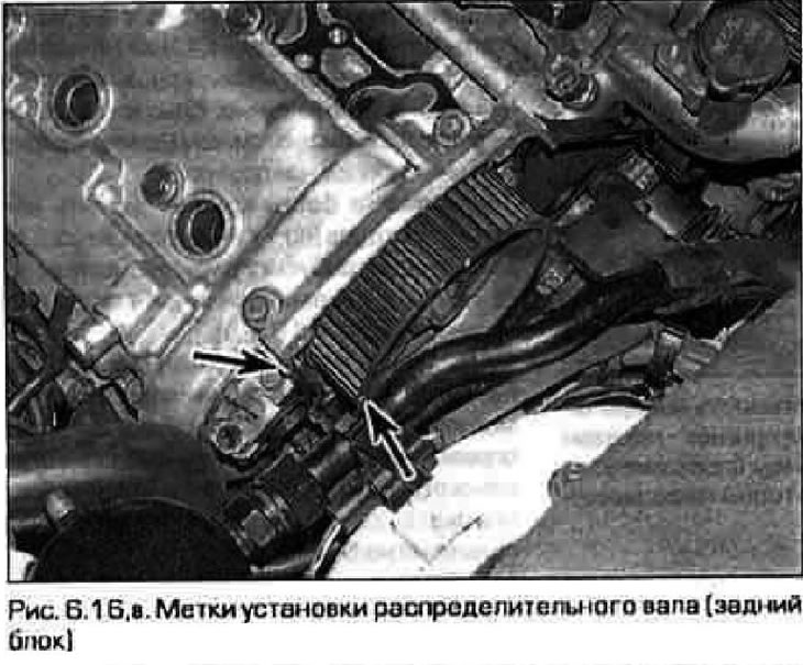
16. Make sure that the marks on the camshaft and crankshaft are aligned with the pointers (pic. 6.16, a-c).
 |  |
17. Turn out two bolts of the lever of a tensioner of a gear belt and remove the lever. Loosen tensioner bolt (pic. 6.17).

Note. Loosen the bolts gradually and alternately, starting with the bottom bolt.
18. Remove the belt from the crankshaft sprockets and camshafts.
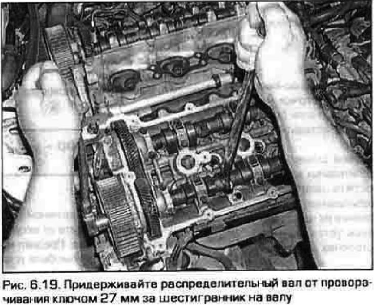
19. If the camshaft sprockets are damaged, now is the time to replace them. Remove the cylinder head covers (see paragraph 4) and loosen the sprocket bolts. When unscrewing the sprocket bolt, hold the wheel against turning with a wrench by the hexagon on the shaft (pic. 6.19). Turn out a bolt and remove an asterisk.
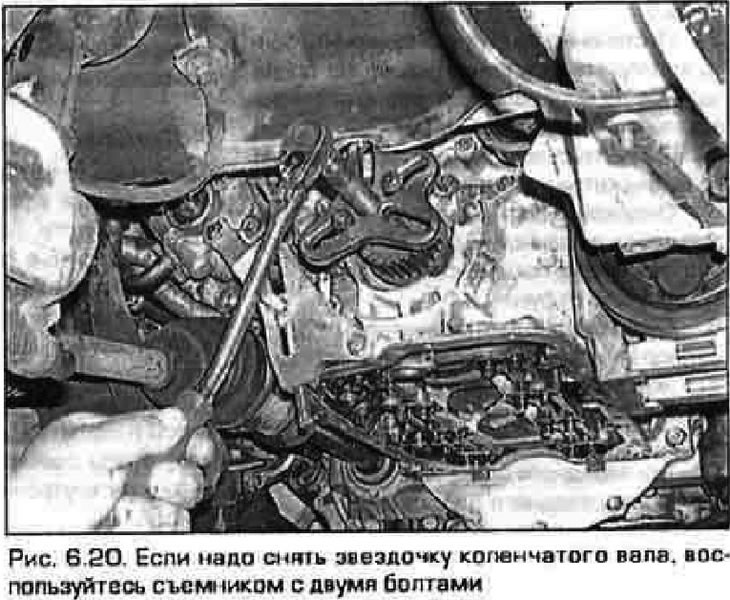
20. To remove the crankshaft sprocket, use a two-bolt puller (pic. 6.20). Do not use a puller with a clip. Be careful not to damage the crankshaft position sensor disc.
Inspection
21. Inspect the belt as indicated in chapter 2A.
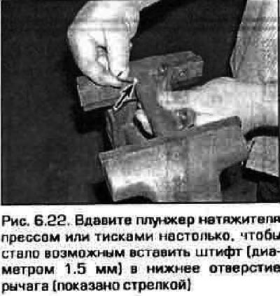
22. Push the tensioner plunger into the arm with a press or vice just enough to allow the pin to be inserted (diameter 1.5 mm) into the bottom hole (pic. 6.22).
23. Check up, whether idle rollers of a belt rotate freely.
Installation
24. Clean the front side of the engine in the belt area from dirt and traces of oil.
25. If the crankshaft sprocket was removed, install it with a flange on the side of the engine (see fig. 6.16,a).
26. Temporarily screw in the crankshaft pulley mounting bolt and turn the crankshaft counterclockwise until the mark on the sprocket aligns with the pointer on the engine wall.
27. Put on a gear belt on asterisks. If an old belt is being installed, then align the marks on the belt and sprockets made when the belt was removed.
28. Turn the crankshaft clockwise until the alignment marks on the crankshaft sprocket are aligned. Do not let the camshafts turn further than their locating queens. In this case, all the slack in the belt will fall on the tensioner branch, and the rest of the belt should be taut.
29. Reinstall the tensioner lever with the plunger recessed and locked in this position. Tighten the lever bolts to the required torque.
30. Remove the retainer from the tensioner lever. Rotate the crankshaft two full turns (720°). Check if the installation marks match (see fig. 6.16, a-c). If the marks do not match, repeat the belt installation procedure. DO NOT start the engine unless you are absolutely sure that the belt is installed correctly. Incorrect belt installation will result in serious engine damage that will require costly repairs.
31. Tighten the tensioner bolt to the required torque.
16. Establish the remained details in sequence, return to their removal.