MazBook.ru
English Русский
Български
Беларускі
Український
Српски
Hrvatski
Română
Polski
Slovenský
Magyar
• Bookmark • Sitemap • Contacts •   
Cars Opel Cars Ford Cars Volkswagen Cars Audi Cars Kia Cars Renault Cars Peugeot


Familia Capella Mazda3 Mazda6 CX-? Others Articles
Capella 3 (1982-1992, petrol) Capella 3 and 4 (1982-1992) Capella 4 (1987-1992) Capella 5 (1991-1997) Capella 6 (1997-2005, petrol)

Mass Air Flow Sensor — checking and replacing (Mazda Capella GF)

  • Home
  • Mazda Capella
  • Capella GF (1997-2005)
  • Power unit
  • Control system
  • Mass Air Flow Sensor — checking and replacing
0
Contents: Examination ⇓ All 4-cylinder and V-shaped engines…⇓ V-shaped engines produced from 1993…⇓
1. The air flow sensor is located in the inlet duct. Depending on the model, the sensor contains a converter with a heated wire or a valve with a potentiometer. The sensor signal is fed to the input of the control unit, which calculates the required amount of fuel supplied to the engine, i.e. the width of the injector control pulse

Examination


2. Remove the sensor and inspect it. Check for dirt on the inlet screen, especially if the vehicle is equipped with an OBD-I diagnostic system and if the system has detected a fault code 158. If the screen is clogged, clean it. On 1993 to 1997 V-engines, push the throttle valve from the intake side and make sure it moves back and forth smoothly without binding. Install the sensor in place and ensure that its seating surfaces are well sealed and do not allow air to pass through.

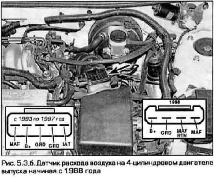
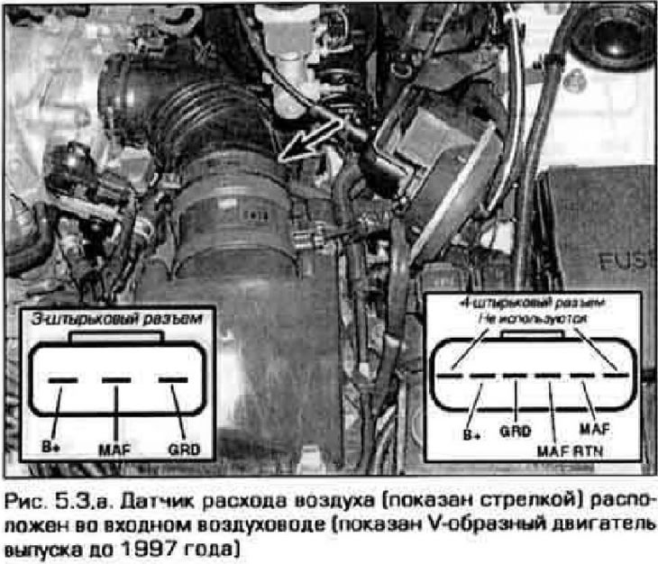
3. Connect the voltmeter with thin probes from the outside of the connector to the B+ and GRD contacts (figure 5.3, a, b). Turn on the ignition. The voltmeter should show the battery voltage. If there is no voltage, disconnect the connector and check the integrity of the ground connection to the GRD contact.
  • a) No voltage and no ground connection: Check the ground circuit.
  • b) No voltage, mass connected: check the power supply target.

Repair the chain if necessary.
Repair the chain if necessary.


Repair the chain if necessary.


All 4-cylinder and V-shaped engines produced since 1998


4. Measure the voltage from the outside of the connector at the MAF contact - first with the engine off, then with the engine idling (see figure 5.3.6).

5. If the sensor has a 3-pin connector, the voltage when the engine is not running should be within 1.0-15 V, and when idling - 1.5-5.0 V.

6. If the sensor has a 4-pin connector, the voltage when the engine is not running should be around zero, and when idling - 0.6-0.7 V (on engines produced since 1998 (0.6-1.1 V).

7. Increase engine speed and apply pressure. how the voltage changes. It should gradually increase to approximately 2.0 V. Voltage surges indicate that the sensor is faulty.

V-shaped engines produced from 1993 to 1997


8. Disconnect the air duct from the sensor (to do this, push the flap inside the sensor). Turn on the ignition, but do not start the engine.

9. Measure the voltage at the MAE contact on the outside of the connector (connect the second probe of the voltmeter to the GND contact) (see Figure 5.3,a). When the valve is closed, the voltage should be 4.0 V. As the valve moves inward, the voltage should decrease as follows:
  • a) Open 1/4 - 2.4 V
  • b) Open 1/2-1.6 S
  • c) Open 3/4-0 Q 8
  • d) Fully open - 0.4 V

All models


10. Reinstall the air duct (if it was removed).

Note: If you experience drivability issues and the above tests do not reveal any fault, have the sensor checked by a specialist. Not all sensor faults can be detected with a voltmeter. The ECU detects this type of malfunction and the diagnostic system can store a corresponding code.


Replacement


11. Disconnect the negative cable from the battery.

Caution: If your vehicle's audio system is equipped with a theft-deterrent feature, make sure you have the unlock code before disconnecting the battery.


12. Disconnect the electrical connector from the air flow sensor.

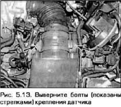
13. Loosen the nuts or bolts and remove the sensor (figure 5.13).
13. Loosen the nuts or bolts and remove the sensor (figure 5.13).


14. Installation is carried out in reverse order.
This article is available at: russian, bulgarian, belarusian, ukrainian, serbian, croatian, romanian, polish, slovak, hungarian
This text was checked by: German Vorobyov
Share with friends on social networks:

Previous
Capella 6 » Control system
Next

Throttle Position Sensor — checking, adjusting, and replacing
Electronic control unit (ECU) — removal and installation
On-board diagnostics and fault codes
Basic information about the engine management system
Intake Air Temperature Sensor — checking and replacing
Coolant Temperature Sensor — checking and replacing
Crankshaft Position Sensor — checking and replacing
Camshaft Position Sensor — checking and replacing
Power Steering Hydraulic Pressure Sensor — checking and replacing
More articles on repairing other Mazda models
Checking the throttle position sensor Mazda Familia 6 (1989-1994)
Checking the level and replacing oil in the manual transmission Mazda3 BK (2003-2009)
Checking and replacing oil in a manual transmission Mazda6 GG (2002-2008)
Mass Air Flow/Intake Air Temperature Sensor #1 Mazda CX-5KE (2012-2017)
Mass Air Flow Sensor / Intake Air Temperature Sensor #2 Mazda BT-50 (1) (2006-2011)
Link in different formats to this article
Comments and feedback from visitors
No comments yet


How much will 43 + 43 ?


Capella 6 (1997-2005, petrol) 
  • General information
  • Introduction to guide
  • User manual
  • Troubleshooting
  • Maintenance
  • Power unit
  • 4-cylinder engines
  • 6-cylinder engines
  • Engine overhaul
  • Cooling and ventilation
  • Power and exhaust systems
  • Engine electrics
  • Control system
  • Transmission
  • Mechanical gearbox
  • Automatic gearbox
  • Clutch and drive shafts
  • Chassis
  • Brake system
  • Car suspension
  • Steering
  • Body
  • Exterior (external elements)
  • Interior (internal elements)
  • Doors, windows and locks
  • Electrical equipment
  • Equipment and devices
  • Electrical circuits
Capella 5 (1991-1997) 
  • General information
  • User manual
  • Maintenance
  • Helpful hints
  • Power unit
  • Petrol engines 1.6 and 1.8
  • Petrol engines 2.0
  • 2.5 petrol engines
  • Overhaul engines 1.6 and 1.8
  • Overhaul engines 2.0 and 2.5
  • Diesel engine 2.0
  • Engine electrics
  • Cooling system
  • Air conditioner
  • Carburetor Nikki 30/34
  • Power system (1.6 and 1.8)
  • Power system (2.0 and 2.5)
  • Control system
  • Transmission
  • Mechanical gearbox
  • Automatic gearbox
  • Clutch and axles
  • Chassis
  • Brake system
  • Suspension and wheels
  • Steering
  • Body
  • Exterior (external elements)
  • Interior (internal elements)
  • Doors and windows
  • Electrical equipment
  • Equipment and devices
  • Electrical circuits
Capella 4 (1987-1992) 
  • General information
  • Introduction to manual
  • Vehicle specifications
  • Power unit
  • Engine repair
  • Lubrication system
  • Cooling system
  • Fuel system (carburetor)
  • Fuel injection (FE)
  • Fuel injection (DOHC)
  • Fuel system (diesel)
  • Ignition system
  • Transmission
  • Clutch
  • Gearbox
  • Drive shafts
  • Chassis
  • Front suspension
  • Rear suspension
  • Steering system
  • Brake system
  • Electrical equipment
  • Equipment and devices
  • Electrical circuits
Capella 3 and 4 (1982-1992) 
  • General information
  • User manual
  • Maintenance
  • Power unit
  • Gasoline engine
  • Engine overhaul (gasoline)
  • Diesel engine
  • Cooling and heating
  • Supply system
  • Ignition system
  • Emission reduction
  • Transmission
  • Clutch
  • Mechanical gearbox
  • Automatic gearbox
  • Drive shafts
  • Chassis
  • Brake system
  • Suspension and wheels
  • Steering
  • Body
  • Exterior (external elements)
  • Interior (internal elements)
  • Electrical equipment
  • Equipment and devices
  • Power devices
  • Electrical circuits
Capella 3 (1982-1992, petrol) 
  • General information
  • User manual
  • Maintenance
  • Troubleshooting
  • Late models
  • Power unit
  • Engine in car
  • Engine overhaul
  • Cooling and heating system
  • Fuel and exhaust system
  • Engine electrical system
  • Emission control system
  • Transmission
  • Mechanical gearbox
  • Automatic gearbox
  • Clutch and drive shafts
  • Chassis
  • Brake system
  • Suspension and wheels
  • Steering
  • Body
  • Exterior (external elements)
  • Interior (internal elements)
  • Electrical equipment
  • Equipment and devices
  • Lighting and lamps
  • Electrical circuits
MazBook.ru © 2018–2026 · Mobile version · Articles and news · Sitemap: EN BG BY UA RS HR RO PL SK HU · Feedback · Site search · Add to bookmarks Familia 5 (BF) · Familia 6 (BG) · Capella 3 (GC) · Capella 3 and 4 (GC) · Capella 4 (GD) · Capella 5 (GE) · Capella 6 (GF) · Mazda3 BK · Mazda6 GG · CX-5KE · Mazda 121 (3) · Mazda BT-50 (1) ·
By continuing to use the site, you agree to the use of cookies 🔐