


Contents: Examination ⇓ Replacement (sensor #2) ⇓
Examination
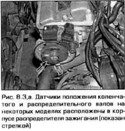
1. The crankshaft position sensor determines the timing and order of fuel injection and ignition in the engine cylinders. This same sensor also measures the crankshaft speed. On early models, the sensor was located in the ignition distributor. On later models, in addition to the sensor in the distributor, another sensor is installed next to the crankshaft pulley. On engines produced since 1998, equipped with an ignition system without a distributor, only one crankshaft position sensor remains - next to the pulley. A sensor malfunction is detected by the diagnostic system and a corresponding code appears in the system memory (see paragraph 2).
Sensor in the ignition distributor (sensor No. 1)
2. Remove the ignition distributor from the engine and reconnect the larger of the two connectors.
Caution: Do not connect the 3-pin connector as this will cause the coil to generate a spark during the test below.
Also disconnect the wiring connector to the injectors so that the injectors will not operate during the upcoming test.
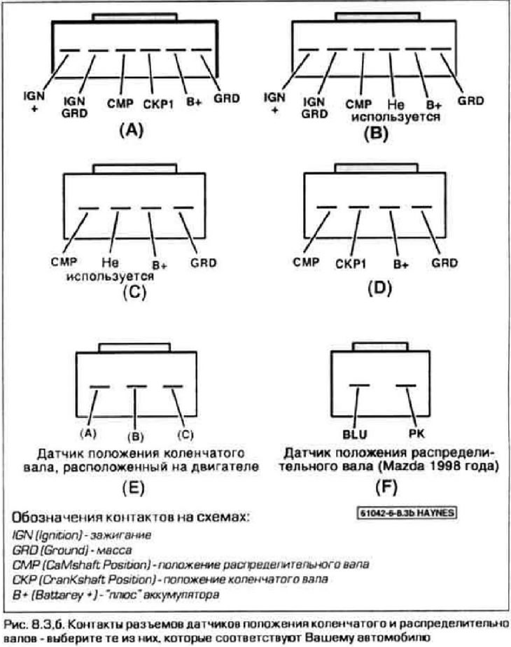
3. Measure the voltage at the SKR1 contact on the outside of the connector (connect the second probe of the voltmeter to the GRD contact) (figure 8.3, a, b). With the ignition on, turn the distributor rotor by hand and observe the voltage. For one revolution of the rotor, the voltmeter should register one pulse per cylinder. In other words, for each revolution of the rotor there should be four pulses on a 4-cylinder engine or 6 pulses on a V-shaped engine. The speed of rotation of the rotor does not matter.
(The primary source is the website: Mazbook)
4. If the test does not produce the specified results, replace the sensor. The sensor may not be supplied as a separate spare part. In this case, you will have to replace the entire distributor assembly (see chapter 5). Check this question with your spare parts store.
Sensor located on the engine (sensor no. 2)
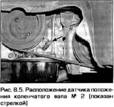
5. Measure the gap between the sensor tip and its gear on the crankshaft (figure 8 5). It should be within 0.5-1.5 mm. The gap is not adjustable, and if it is outside the specified range, replace the sensor or bracket (if the model requires bracket removal).
6. To check the sensor, disconnect its electrical connector and measure the resistance between contacts A and B (see Figure 8.3,b). The resistance should be approximately 550 ohms (within the range from 520 to 580 Ohm). If this is not the case, replace the sensor.
Replacement (sensor #2)
9. Disconnect the negative cable from the battery.
Caution: If your vehicle's audio system is equipped with a theft-deterrent feature, make sure you have the unlock code before disconnecting the battery.
10. Disconnect the electrical connector from the sensor and release the wiring from clamps and ties.
11. Unscrew the sensor mounting bolts and remove it from the engine.
12. Installation is carried out in reverse order. Check the clearance between the tip and the sensor wheel and make sure it is within the limits specified in paragraph. 5.