


Contents: Examination ⇓ Replacement ⇓
Examination
1. The oxygen sensor monitors the oxygen content in the exhaust gas stream. Oxygen contained in the exhaust gases reacts with the sensor, which causes the sensor signal voltage to change within the range of 0.1 V (too much oxygen, lean mixture) up to 0.9 V (low oxygen, rich mixture). The ECU receives a signal from the sensor and calculates the ratio of fuel and air in the working mixture. Correction of this ratio is carried out by changing the duration of the open state of the fuel injectors. The ideal working mixture is considered to be one that consists of 14.7 parts air and 1 part fuel. With this air-fuel ratio, almost complete combustion of the fuel is achieved, which allows the catalytic converter to operate at maximum efficiency. The ECU strives to maintain the composition of the working mixture at an optimal level under all engine operating conditions. The OBD-II diagnostic system contains at least two oxygen sensors: a primary sensor located before the neutralizer and a secondary sensor located after the neutralizer. Later models with a V-shaped engine even have four oxygen sensors. By comparing the composition of gases before and after the neutralizer, the sensors allow monitoring its efficiency.
2. Until the oxygen sensor reaches operating temperature (about 300°C), it does not generate a signal. Therefore, when the engine warms up, the ECU operates in a mode without feedback.
3. If the engine has reached operating temperature and/or more than 2 minutes have passed since starting, and the oxygen sensor voltage remains constant and does not exceed 0.45 V at engine speeds of 1500 rpm or higher, a fault code will be logged in the diagnostic unit. Additional codes may also appear if the sensor heating circuit is faulty.
4. If the oxygen sensor or its target is faulty, the control unit begins to operate in a mode without feedback, i.e. the composition of the working mixture is determined by the program stored in the ECU memory and is not adjusted in accordance with the signal from the oxygen sensor.
5. Normal operation of the oxygen sensor depends on four conditions:
- a) Electrical circuit - Low voltage at the sensor output may be due to contamination or oxidation of the contacts in the circuit connections. Always check the condition of all contacts in the oxygen sensor circuit first.
- b) Intake of outside air - The sensor is designed in such a way that outside air must enter its internal cavity. Whenever removing and installing or replacing the sensor, make sure that the sensor air passages are not clogged.
- c) Maintaining Operating Temperature - The control unit does not receive signals from the sensor until it reaches a temperature of 320°C. This factor must be taken into account when assessing the sensor's performance.
- d) Use of unleaded gasoline - Only unleaded gasoline must be used for the sensor to operate. Make sure that the car's tank contains this type of gasoline.
6. In addition to the above conditions, the following precautions must be observed when servicing the sensor:
- a) The oxygen sensor has a flexible wire with a connector that is not disconnected from the sensor. Damage to the wire or connector may adversely affect the operation of the sensor.
- b) Grease and dirt must not come into contact with the connector and the working surface of the sensor.
- c) Do not use any solvents to clean the oxygen sensor.
- d) Handle the sensor with care - do not drop it or expose it to impacts.
- d) The silicone cover of the sensor must be installed correctly to prevent it from melting and to ensure proper operation of the sensor.
7. Locate the electrical connector of the oxygen sensor (Fig. 11.7) and, without disconnecting it, connect the voltmeter with long thin probes from the outside of the connector to the signal contact and to the ground contact. Tighten the parking brake and set the gearshift lever to the "neutral" position (manual transmission) or "parking" (automatic transmission). Raise the front of the car and support it on stands.

8. Check the sensor signal under operating conditions. To do this, start the engine and observe the voltmeter readings as the engine warms up.
Caution! Be careful not to burn yourself on hot exhaust system components.
Note: Secondary oxygen sensors respond to rich or lean mixtures to a much lesser degree than the primary sensor because the catalytic converter converts CO, HC, and NOx molecules into CO₂ and H₂O using excess oxygen.
9. When the engine is cold, the oxygen sensor produces a constant voltage at the output level of approximately 0.1-0.2 V. The control system operates without feedback. After about two minutes, when the sensor warms up and reaches operating temperature. the voltage at its output will begin to rise from 0.1 to 0.9 V (feedback mode is enabled). If the sensor does not enter feedback mode or it takes too long to do so. Replace the sensor.
10. Also check the sensor heater. Disconnect the wiring from the sensor and connect a voltmeter to the heater contacts (check the connector contacts using the electrical diagrams at the end of Chapter 12). The heater resistance should be within 10-40 Ohms.
11. Check the power supply to the heater (check the contacts using the electrical diagrams). When the ignition is on and the engine is not running, battery voltage should be supplied to the heater. If there is no voltage, check the main relay, ECU and sensor circuits.
12. If during the checks any deviations of the sensor parameters from the specified ones are detected, replace the sensor.
Replacement
13. Since the sensor is installed in the exhaust system, which contracts when cooled, it may not be possible to remove the sensor from a cold engine. To avoid putting unnecessary stress on the sensor, start the engine and warm it up for one to two minutes, then turn it off. Be careful not to burn yourself on hot exhaust system parts.
14. To access the sensor on some models, you may need to raise the front of the vehicle and support it on stands.
15. Disconnect the electrical connector from the sensor.
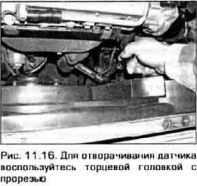
16. Carefully unscrew the sensor from the exhaust manifold (primary) or from the exhaust pipe (secondary) (figure 11.16).
17. When installing the sensor, it is recommended to use a compound that prevents the threaded connections from seizing. The new sensor is already coated with this composition. But when reusing an old sensor, an anti-seize compound must be applied to the sensor threads.
18. Screw in the sensor and tighten it securely.
19. Connect the connector at the end of the sensor wires to the engine wiring harness.
20. Lower the vehicle, test drive it and ensure that no fault codes are displayed.