
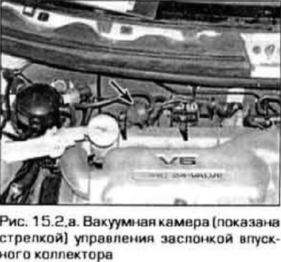
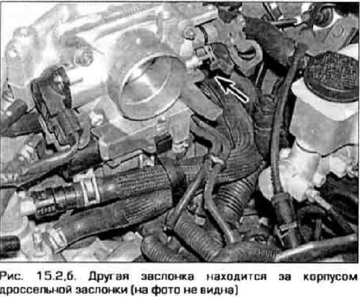
2. Locate damper vacuum chambers (pic. 15.2, a, b).
3. Warm up the engine. While idling, quickly turn and release the throttle to increase engine speed. The linkages of the path configuration control dampers should move. If this does not happen, check the vacuum hoses of the executive chambers for cracks, poor fastening. If the hoses are OK, check the other parts of the system as follows.
Vacuum actuators
Examination
4. With the engine stopped, disconnect the vacuum hoses from the actuators. Connect a vacuum pump to the device and create a vacuum in the chamber. Throttle control rod should move. If this does not happen, replace the actuator.
Replacement
5. Disconnect the vacuum hose from the actuator. Disconnect the thrust from the air damper, unscrew the bolts securing the actuator and remove it from the engine.
6. Installation is carried out in reverse order.
Solenoid valves
Examination
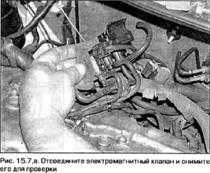
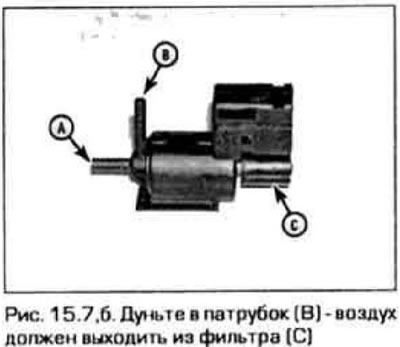
7. Disconnect the vacuum hoses from the solenoid valve, disconnect the electrical connectors and remove the valves (pic. 15.7.a). Blow into nozzle B (pic. 15.7,b). Air must exit filter C at the end of the valve.
8. Disconnect the electrical connector from the valve and connect the battery voltage to the valve terminals (pic. 15.8).
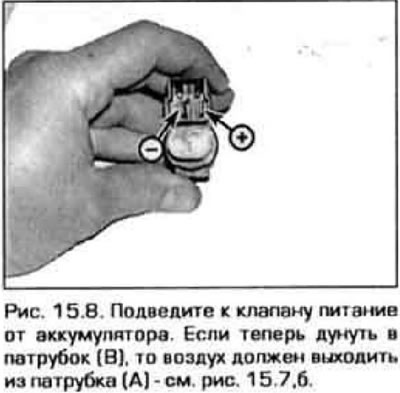
9. Doom» those in nozzle B (see fig. 15.7,b). Air should now come out of port A.
10. If the valve behaves differently, replace it.
Replacement
11. Disconnect from the valve hoses and an electric socket.
12. Unfasten the valve from the bracket (see fig. 15.7,a).
13. Install to dads in reverse order.
Vacuum chambers
Examination
14. Vacuum chambers are located on the underside of the intake manifold. Remove manifold (see chapter 2B) and inspect the chambers for cracks and dents.
Replacement
15. Remove the intake manifold (see chapter 2B).
16. Disconnect the vacuum hoses from the chambers. Turn away bolts of fastening of chambers and remove them from a collector.
17. Installation is carried out in reverse order.