
General information
1. The recirculation system reduces the content of nitrogen oxides in the exhaust gases, directing them into the intake manifold for afterburning in the combustion chambers.
2. The recirculation system includes a recirculation valve, a valve position sensor, a BCU and various sensors. The BEU is programmed in such a way as to ensure optimal opening of the recirculation valve under any engine operating conditions. In the event of a malfunction in the system, the BEU closes the recirculation valve and stops the flow of exhaust gases into the combustion chambers.
Examination
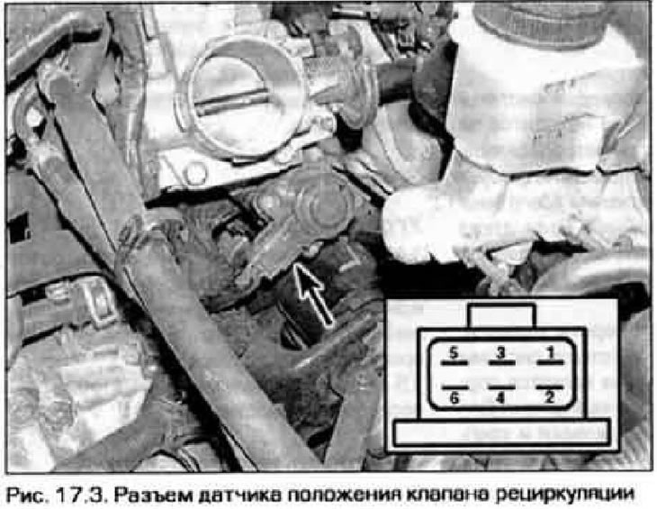
3. To check the recirculation valve position sensor, disconnect the electrical connector from it and measure the resistance between the contacts 1 and 3, 3 and 5, 2 and 4, 4 and 6 of the valve (pic. 17.3). All resistance values should be approximately equal to 22 ohms. If it is not, replace the sensor.
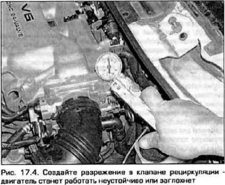
4. Warm up the engine to operating temperature. Disconnect the vacuum hose from the recirculation valve and connect a vacuum pump in its place (pic. 17.4). With the engine running at idle, create a vacuum in the valve. In this case, the engine speed becomes unstable and the engine may stall. If there is no change, then the valve is faulty and needs to be replaced.
5. Locate the recirculation control solenoid valve. Disconnect from it vacuum hoses and electroconducting. Connect the electromagnet directly from the battery. If you blow into one pipe of the valve, then the air should come out of the other pipe (see fig. 15.7,b and 15.8). Disconnect valve power. Now, if you blow into the pipe closest to the electromagnet, then the air should come out of the outlet at the end of the valve. It should not be possible to blow air through the nozzle farthest from the magnet.
6. Further verification of the recirculation control system requires special equipment.
Recirculation valve replacement
7. Disconnect the valve position sensor electrical connector.
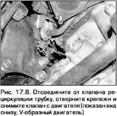
8. Disconnect the tube from the valve, unscrew the valve fasteners and remove it from the engine (pic. 17.8).
9. Clean mating surfaces of valve and adapter.
10. Install the valve with a new gasket. Tighten fastener securely.
11. Connect the electrical connector to the valve.