
MazBook.ru
English Русский
Български
Беларускі
Український
Српски
Hrvatski
Română
Polski
Slovenský
Magyar
• Bookmark • Sitemap • Contacts •   
Cars Opel Cars Ford Cars Volkswagen Cars Audi Cars Kia Cars Renault Cars Peugeot


Familia Capella Mazda3 Mazda6 CX-? Others Articles
Capella 3 (1982-1992, petrol) Capella 3 and 4 (1982-1992) Capella 4 (1987-1992) Capella 5 (1991-1997) Capella 6 (1997-2005, petrol)

Throttle Position Sensor — checking, adjusting, and replacing (Mazda Capella GF)

  • Home
  • Mazda Capella
  • Capella GF (1997-2005)
  • Power unit
  • Control system
  • Throttle Position Sensor — checking, adjusting, and replacing
0
Contents: Examination ⇓ Adjustment ⇓ Replacement ⇓

Examination


1. The throttle position sensor is mounted on the throttle body and connected to the throttle shaft. In accordance with the angle of rotation of the valve, the ECU regulates the supply of fuel to the engine cylinders. A faulty or loose sensor can cause erratic engine operation because the ECU interprets the sensor's vibration as throttle valve movement. The diagnostic system detects a malfunction of the throttle sensor and generates a corresponding code (see paragraph 2).

2. Check the voltage supply from the control unit to the sensor. To do this, disconnect the electrical connector of the sensor and connect a voltmeter to the REF (+) and GND (-) contacts (figure 4.2). With the ignition on (the engine is not working) the voltmeter should show approximately 5.0 V. If there is no voltage, then either there is a break in the wiring from the ignition control unit to the sensor, or the ignition control unit is faulty.
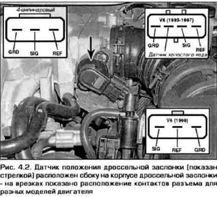
2. Check the voltage supply from the control unit to the sensor. To do this, disconnect the…


3. Now check the sensor potentiometer. Connect the sensor connector and connect the voltmeter to the SIG (+) and GNO (-) connector contacts on the back side (using thin probes or needles). Turn on the ignition (do not start the engine). Close the damper completely. The voltage at the sensor contacts should be between 0.5 and 1.0 V. Now slowly open the valve and observe the change in voltage - it should increase slowly and smoothly. With the throttle fully open, the voltage should stop at 3.5-5.0 V.


4. On 4-cylinder engines produced in 1993, the throttle position sensor is structurally integrated into the throttle body and cannot be replaced separately from it. The sensor cannot be adjusted on these models. On all other models, the sensor can be adjusted. If, when checking the sensor, the signal voltage does not change as specified in paragraph. 3, try adjusting the sensor. If adjustment does not help, replace the sensor.

Adjustment


5. Loosen the sensor mounting screws (figure 4.5).

The original text is published on: www.MazBook.ru
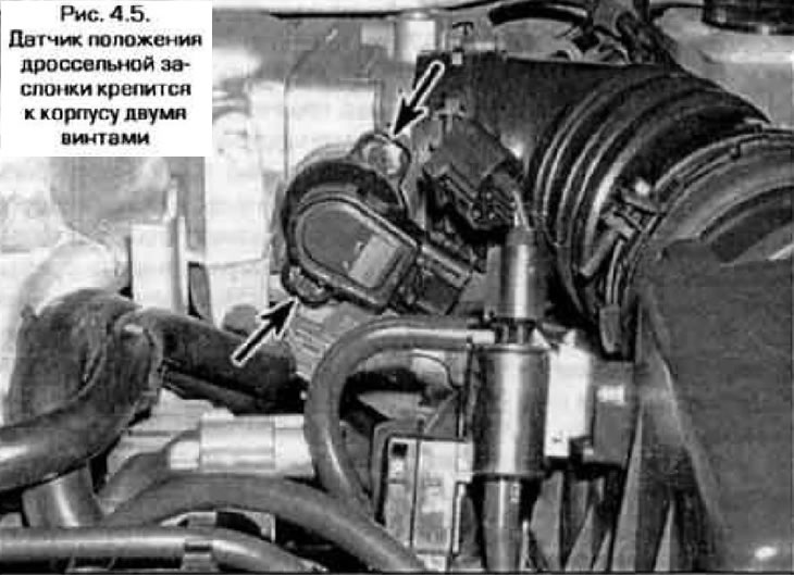
5. Loosen the sensor mounting screws (figure 4.5).


6. Connect the voltmeter to the SIG and GND contacts of the sensor connector (see figure 4.2).

7. Set the damper to the fully closed position and rotate the sensor until the signal voltage is within 0.5-1.0 V. Tighten the sensor mounting screws.

8. Turn the damper to the fully open position. The signal voltage should be in the range of 3.5-5.0 V.

9. If the required voltage values cannot be obtained in both throttle positions, replace the sensor.

Replacement


10. This procedure is suitable for all models except 1993 4-cylinder engines. On engines of this model, the sensor is made integral with the valve body and can only be replaced as an assembly with the body.


11. Disconnect the sensor electrical connector. Loosen the screws that secure it and remove the sensor from the valve body (see figure 4.5).

12. The sensor is installed in the reverse order of removal. Align the tabs on the sensor body with the slots on the valve body. Screw in the screws, adjust the position of the sensor as above, then tighten the screws completely.
This article is available at: russian, bulgarian, belarusian, ukrainian, serbian, croatian, romanian, polish, slovak, hungarian
This text was checked by: German Vorobyov
Share with friends on social networks:

Previous
Capella 6 » Control system
Next

Electronic control unit (ECU) — removal and installation
On-board diagnostics and fault codes
Basic information about the engine management system
Mass Air Flow Sensor — checking and replacing
Intake Air Temperature Sensor — checking and replacing
Coolant Temperature Sensor — checking and replacing
Crankshaft Position Sensor — checking and replacing
Camshaft Position Sensor — checking and replacing
More articles on repairing other Mazda models
Checking/Adjusting the Throttle Position Sensor Mazda Familia 6 (1989-1994)
Checking and adjusting the throttle cable (diesel) Mazda3 BK (2003-2009)
Adjusting the longitudinal position of the seats Mazda6 GG (2002-2008)
Throttle Position Sensor Mazda CX-5KE (2012-2017)
Checking and adjusting valve clearance Mazda 121 (3) (1996-2003)
Link in different formats to this article
Comments and feedback from visitors
No comments yet


How much will 12 + 45 ?


Capella 6 (1997-2005, petrol) 
  • General information
  • Introduction to guide
  • User manual
  • Troubleshooting
  • Maintenance
  • Power unit
  • 4-cylinder engines
  • 6-cylinder engines
  • Engine overhaul
  • Cooling and ventilation
  • Power and exhaust systems
  • Engine electrics
  • Control system
  • Transmission
  • Mechanical gearbox
  • Automatic gearbox
  • Clutch and drive shafts
  • Chassis
  • Brake system
  • Car suspension
  • Steering
  • Body
  • Exterior (external elements)
  • Interior (internal elements)
  • Doors, windows and locks
  • Electrical equipment
  • Equipment and devices
  • Electrical circuits
Capella 5 (1991-1997) 
  • General information
  • User manual
  • Maintenance
  • Helpful hints
  • Power unit
  • Petrol engines 1.6 and 1.8
  • Petrol engines 2.0
  • 2.5 petrol engines
  • Overhaul engines 1.6 and 1.8
  • Overhaul engines 2.0 and 2.5
  • Diesel engine 2.0
  • Engine electrics
  • Cooling system
  • Air conditioner
  • Carburetor Nikki 30/34
  • Power system (1.6 and 1.8)
  • Power system (2.0 and 2.5)
  • Control system
  • Transmission
  • Mechanical gearbox
  • Automatic gearbox
  • Clutch and axles
  • Chassis
  • Brake system
  • Suspension and wheels
  • Steering
  • Body
  • Exterior (external elements)
  • Interior (internal elements)
  • Doors and windows
  • Electrical equipment
  • Equipment and devices
  • Electrical circuits
Capella 4 (1987-1992) 
  • General information
  • Introduction to manual
  • Vehicle specifications
  • Power unit
  • Engine repair
  • Lubrication system
  • Cooling system
  • Fuel system (carburetor)
  • Fuel injection (FE)
  • Fuel injection (DOHC)
  • Fuel system (diesel)
  • Ignition system
  • Transmission
  • Clutch
  • Gearbox
  • Drive shafts
  • Chassis
  • Front suspension
  • Rear suspension
  • Steering system
  • Brake system
  • Electrical equipment
  • Equipment and devices
  • Electrical circuits
Capella 3 and 4 (1982-1992) 
  • General information
  • User manual
  • Maintenance
  • Power unit
  • Gasoline engine
  • Engine overhaul (gasoline)
  • Diesel engine
  • Cooling and heating
  • Supply system
  • Ignition system
  • Emission reduction
  • Transmission
  • Clutch
  • Mechanical gearbox
  • Automatic gearbox
  • Drive shafts
  • Chassis
  • Brake system
  • Suspension and wheels
  • Steering
  • Body
  • Exterior (external elements)
  • Interior (internal elements)
  • Electrical equipment
  • Equipment and devices
  • Power devices
  • Electrical circuits
Capella 3 (1982-1992, petrol) 
  • General information
  • User manual
  • Maintenance
  • Troubleshooting
  • Late models
  • Power unit
  • Engine in car
  • Engine overhaul
  • Cooling and heating system
  • Fuel and exhaust system
  • Engine electrical system
  • Emission control system
  • Transmission
  • Mechanical gearbox
  • Automatic gearbox
  • Clutch and drive shafts
  • Chassis
  • Brake system
  • Suspension and wheels
  • Steering
  • Body
  • Exterior (external elements)
  • Interior (internal elements)
  • Electrical equipment
  • Equipment and devices
  • Lighting and lamps
  • Electrical circuits
MazBook.ru © 2018–2026 · Mobile version · Articles and news · Sitemap: EN BG BY UA RS HR RO PL SK HU · Feedback · Site search · Add to bookmarks Familia 5 (BF) · Familia 6 (BG) · Capella 3 (GC) · Capella 3 and 4 (GC) · Capella 4 (GD) · Capella 5 (GE) · Capella 6 (GF) · Mazda3 BK · Mazda6 GG · CX-5KE · Mazda 121 (3) · Mazda BT-50 (1) ·
By continuing to use the site, you agree to the use of cookies 🔐