


Contents: Tools needed for troubleshooting ⇓ OBD-I system (days of early models…⇓ OBD-II system (models produced since…⇓ System sensors (OBD-I and OBD-II) ⇓ Executive devices of the system…⇓
Tools needed for troubleshooting
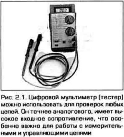
1. A digital multimeter is required to check components related to fuel injection and emissions control systems (figure 2.1). A digital tester should be preferred over its analog predecessor for the following reasons: An analog tester is not able to detect and display changes in voltage, resistance, or current in hundredths or thousandths, as a digital device can. Another advantage of digital instruments is their high input resistance (impedance), which can reach several million ohms. Since the voltmeter is connected in parallel to the circuit being tested, it's important that the current doesn't branch off into the instrument's circuit and distort the measurement results. When testing power targets with low resistance and a fairly high voltage level, for example, 9-12 V, the resistance of the device does not play a significant role. But when working with high-impedance circuits and low voltages, typical of measuring circuits, the high resistance of the device can be very useful. For example, when measuring the signal from an oxygen sensor, even a voltage of 1 V can be significant for troubleshooting.
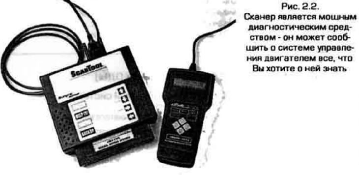
2. Handheld scanners (figure 2.2) are the most effective tool for analyzing engine control systems of modern models. The scanner size must match your car - model and year of manufacture. Sometimes the scanner design allows for the installation of adjacent cartridges designed for specific manufacturers (Ford. GM. Chrysler, etc.). Some manufacturers specialize by sales market - Asia, Europe, North America, etc.
3. Models produced since 1996 are equipped with a more advanced OBD-II on-board diagnostic system. A scanner is required to read fault codes in this system (code reader), specially designed for this system. If there is no scanner and it is not possible to obtain one, then the system can only be diagnosed at a service station that has such equipment.
OBD-I system (days of early models up to 1995)
General information
Note: Common faults are listed in the Troubleshooting section at the beginning of the book.
4. The on-board computer (OBD) has a built-in self-diagnostic system or OBD (On-Board Diagnostics) - on-board diagnostics. which detects malfunctions in the system sensors and notifies the driver about this with the CHECK ENGINE warning light (check the engine). When a malfunction occurs, the diagnostic system generates a malfunction code and stores it in the computer memory. The fault code remains stored until it is forcibly cleared from memory or the fault is corrected.
5. When the ignition is turned on, the CHECK ENGINE light should come on. This means that the system is checking the functionality of the alarm. After starting the engine, the light should go out. If the light does not go out, it means the diagnostic system has detected a malfunction.
Reading fault codes
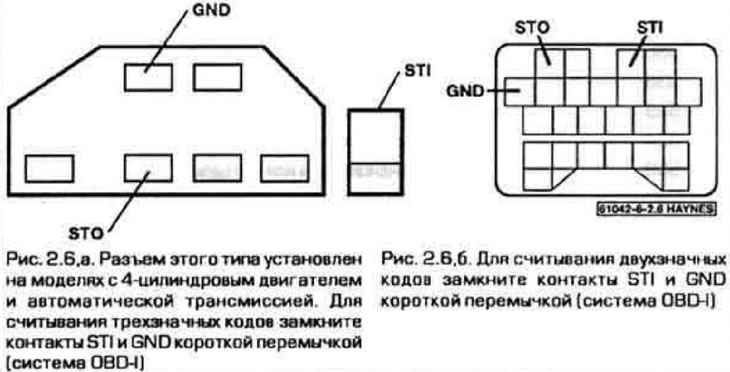
6. To access the diagnostic system, first locate the diagnostic connector, which should be located on the left (from the driver's side) side of the engine compartment next to the battery. Depending on the model, engine, transmission, etc., the vehicle may be equipped with one of two types of diagnostic connectors (figure 2.6, a, b). Connect the STI and GND connector pins with a short jumper. If desired, you can connect an analog voltmeter or test light to the STO pin (connect the second wire of the voltmeter or light bulb to ground). Error codes can be read by the fluctuations of the voltmeter needle or by the flashing of the light. The CHECK ENGINE light will also flash in the same way.
7. Make sure that. that the voltage at the battery terminals exceeds 11 V, that the gearbox is in neutral, electrical consumers are turned off, the throttle valve is closed and that the engine has warmed up to operating temperature. After this, turn on the ignition, but do not start the engine.
8. The fault code is determined by the number of flashes of the CHECK ENGINE lamp (or a control lamp, if connected). If there are no fault codes in the memory, the light will come on for a while and then go out. If there are fault codes in the memory, the light will show the first digit of the code in long flashes, and the second digit of the code in short flashes. For example, code 34 (idle air control valve malfunction) reproduced by a series of three long flashes and four short ones.
Note: If the move consists of one digit, the light will only flash briefly.
9. Below is a table that lists the codes and their corresponding faults.
OBD-I system codes (two-digit codes)

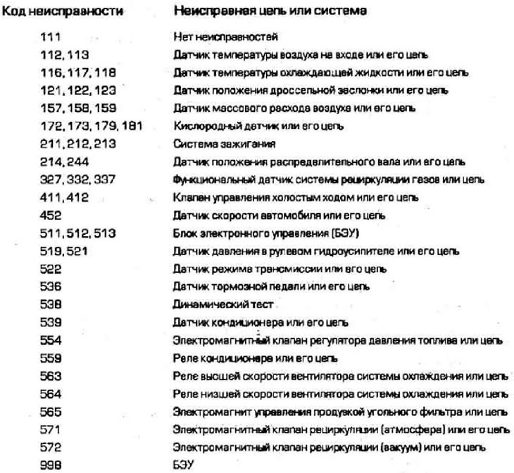
OBD-I system codes (three-digit codes)
Removal codes
10. After checking the codes, remove the jumper from the diagnostic connector and close the connector with the cover. Check the system or circuit in which the fault is found and correct it.
11. After the fault has been corrected, the fault code can be cleared. To do this, disconnect the negative cable from the battery, press the brake pedal and hold it down for at least 5 seconds.
12. After clearing the codes, take the vehicle for a test drive and see if the problem reoccurs.
OBD-II system (models produced since 1996)
General information
Note 1. The sanitary faults are listed in the section Troubleshooting at the beginning of the book.
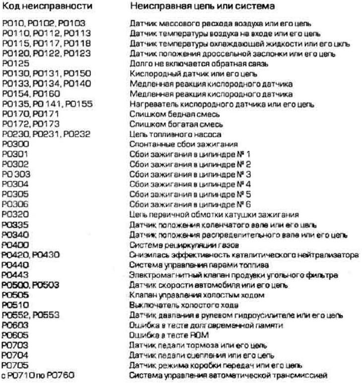
Note 2: This is not a complete list of fault codes generated by the OBD-FL system. Reading codes in this system requires specialized equipment. This text lists only codes common to all vehicles manufactured since 1996 and equipped with the OBD-II diagnostic system. This list does not include codes included in the diagnostic system by specific manufacturers. You can inquire about additional fault codes entered by the manufacturer at your dealer.
13. Since 1994, Ford Motor Company has been equipping its vehicles with a modified OBD-II diagnostic system. This system monitors the emissions control system, detects system malfunctions, and stores information about the malfunctions in the computer's memory. The diagnostic system also checks engine management system sensors and actuators, detects and counts vehicle duty cycles, updates information and clears codes. Access to the OBD-II diagnostic system is only possible using a scanner that connects to the system's 16-pin diagnostic connector. This connector is located under the dashboard on the driver's side (figure 2.13).
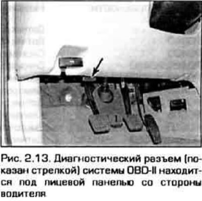
Note: Although Ford began producing the OBD-II system in 1994, the models covered in this book did not receive the system until 1996.
14. The brain of the system is the BEU. located under the front pew foam on the front passenger side. The unit receives information from numerous sensors, as well as from other electrical devices (switches. relays, actuators). Based on the information received, the control unit generates output signals to control actuators—relays, electromagnets, etc. The electronic control unit is programmed to optimize the vehicle's traction and dynamic performance, its fuel efficiency, and minimize harmful emissions.
15. In this regard. although the DBD4I system has an extended warranty, it is not recommended to replace the control unit or system sensors yourself during the warranty period, unless you want to lose it.
Reading trouble codes in the OBD-II system
16. The OBD-II system will illuminate the warning light on the instrument cluster after it detects the same fault in two consecutive operating cycles. The light will remain on until the system detects this fault in three consecutive cycles. Since resetting the fault signal requires specialized equipment, it is recommended to have the system checked periodically at a specialized service station.
17. To retrieve diagnostic codes, a special scanner is required, which is connected to the system's diagnostic connector.
Removal codes
18. To delete codes from the ECU memory, connect the scanner to the diagnostic connector and select the CLEARING CODES mode in the device menu (removing codes). Next, follow the scanner manufacturer's instructions.
Caution: To clear codes, DO NOT DISCONNECT the battery. By disconnecting the power supply to the ECU, you will erase the current information about the engine condition and the control unit will have to obtain this information again. While this is happening, the engine will run intermittently.
OBD-II system codes
System sensors (OBD-I and OBD-II)
19. The oxygen sensor produces a signal in the form of a voltage, which depends on the difference in oxygen content in the exhaust gases and in the surrounding air.
20. Crankshaft position sensor 1 - on some models it is located in the ignition distributor. Notifies the ECU of the position and rotation speed of the crankshaft. The ECU uses this information to calculate fuel cycle timing and spark advance.
21. Crankshaft position sensor 2 is installed on later production models. They perform the same functions as sensor 1, but are located not in the distributor, but next to the crankshaft pulley.
22. The camshaft position sensor provides a signal that the ECU uses to determine the position of piston No. 1 to control the fuel injection sequence.
23. Coolant temperature sensor - provides a voltage signal, which is used by the ECU to correlate the mixture composition, ignition timing, and control the operation of the gas recirculation system.
24. Inlet air temperature sensor - provides the control unit with information about the air temperature entering the air cleaner. The ECU uses the sensor information to adjust fuel delivery, spark advance, and to control the evaporative emission system.
25. Throttle position sensor - provides the ECU with information about the position and movement of the throttle valve. Based on the sensor signal, the ECU determines whether the throttle valve is in a closed, fully open, or intermediate static position.
26. Mass air flow sensor - measures the mass of air entering the engine cylinders. The information is used by the control unit to calculate fuel delivery.
27. Knock sensor - detects detonation and alerts the ECU. Upon receiving the detonation signal, the ECU begins to reduce the ignition timing until the detonation subsides.
28. The vehicle speed sensor transmits information about the vehicle speed to the ECU.
29. EGR valve position sensor - notifies the ECU of the position of the recirculation valve.
30. Fuel tank pressure sensor - is part of the fuel vapor management system and transmits information about the fuel vapor pressure in the tank to the ECU. The ECU uses this information to control the actuators of the carbon filter purge system.
31. Power steering pressure sensor - contact sensor (switch) it is designed to increase the pressure in the transmission control system when maneuvering the vehicle in tight spaces at low speed.
32. Transmission sensors - in addition to the vehicle speed, the ECU receives signals about the rotation speed of the primary and intermediate shafts of the transmission or parts connected to them.
33. Compressor switch - when the compressor switches on, the sensor contacts close and send a signal to the ECU. The ECU interprets the signal as increased engine load and increases idle speed accordingly to prevent the engine from stalling.
34. Brake pedal sensor-combined with the brake light switch. When the brake pad is pressed, the BEU receives a signal that the BEU disables the "cruise control" mode (if it is turned on), reduces ignition timing and changes the fuel delivery cycle during vehicle deceleration.
Executive devices of the system (OBD-I and OBD-II)
35. Fuel injectors - the ECU opens the injectors one by one, in accordance with the order of cylinder operation. In addition, the ECU controls the duration of the injector opening (control pulse width), which determines the amount of fuel entering the cylinder per cycle.
36. Ignition control unit - the unit operates under the control of the BEU. It controls the current of the primary winding of the ignition coil (s) and sets the necessary advance on the BEU signals. On some models, the ignition control unit is located in the distributor, on other models it is located separately in the engine compartment. More detailed information about the ignition control unit is given in chapter 5.
37. Idle Air Control Valve - Controls additional air flow bypassing the throttle valve when it is in the idle position. The degree of valve opening is determined by the ECU.
38. Electromagnetic valve for purging the carbon filter - the carbon filter, which contains fuel vapors, is purged under certain engine operating conditions. Fuel vapors enter the intake manifold and then into the engine cylinders, where they burn in the usual way.