
Removing
1. Remove the generator.
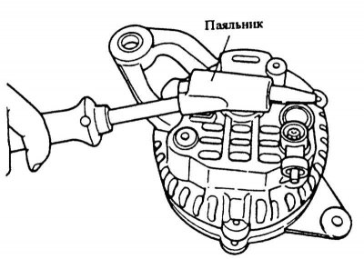
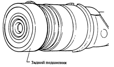
2. Heat the case to 50°-60°C, to do this, hold a 200 W soldering iron over the bearing case for 3-4 minutes.
Attention! If the bearing housing is not heated, the bearing cannot be removed because the rear bearing and the rear mount are very tightly connected to each other.
3. Unscrew and take out 3 through bolts. Insert a flat blade screwdriver between the stator and the front mount and separate the two parts.
Attention! Do not insert the screwdriver too far, otherwise the stator may be scratched. When separating parts, make sure that a compressed spring does not jump out in the area of \u200b\u200bthe rear bearing.
4. Carefully clamp the rotor in a vise and unscrew the central bolt of the belt pulley. Remove the belt pulley with impeller and spacer.
5. Unscrew the rectifier from the rear cover of the generator.
6. Separate the rear attachment and the stator from each other.
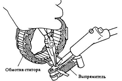
7. Unsolder the stator winding cable from the rectifier holder while holding the terminal with pliers to remove heat from the rectifier. Do not hold the soldering iron for more than 5 seconds.
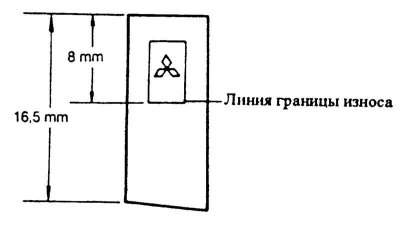
8. Replace carbon brushes if wear limit is reached (length 8 mm or less). To do this, solder the contacts.
9. Check the wear of the slip rings on the rotor, replace if necessary.
10. Check both rotor bearings for ease of movement. replace if necessary. The rear bearing is pressed in, a press is needed to replace.
Installation
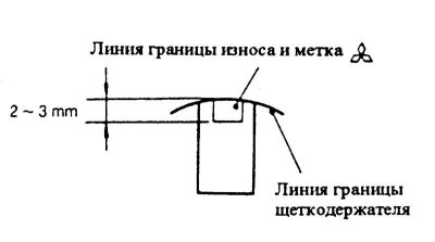
1. Insert the brushes and springs into the holders and solder the contacts. Cut off protruding sections. At the same time, solder the wires so that the line of the wear limit of the brushes is opposite the end of the brush holder 2-3 mm ahead.
2. So that solder bumps do not rise when soldering new brushes, squeeze the contacts of the brushes with pliers.
Attention! Due to the protruding bumps, the contacts become rigid and the brushes become unusable.
3. After installation, check the ease of movement of the new brushes in the holders.
4. Solder the stator cable with the rectifier board, while not overheating the rectifier.
5. Install the rear housing on the rotor and connect.
6. Fit front endshield with spacer bush and collared bush.
7. Install the impeller with belt pulley and spring washer and tighten the nut firmly 60 Nm.
8. Insert the thrust spring into the eccentric groove of the rear bearing. The protruding part of the spring must then enter the deepest part of the groove. The edge of the groove in the deepest place has a chamfer.
Attention! Be sure to check the correct position of the thrust spring, as this reduces the protrusion of the spring relative to the groove, which facilitates assembly. In addition, the spring is not so heavily loaded and due to this, the persistent effect is increased.
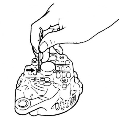
9. Before installation, bend the rectifier connection wires so that they do not touch the rotor. Insert the brushes into the brush holders with your finger, insert the wire into the rear bearing hole (diameter 2 mm, length 40-50 mm), thus keeping the brushes pressed.
10. Assemble the generator housing by pre-heating the fastening with a soldering iron, see paragraph Removal.
11. Screw the housing with 3 through bolts.
Attention! Remove the wire holding the brushes from the hole behind the generator.
12. Make sure that the generator turns freely by hand.
13. Install the generator.
14. Connect the mass cable to the battery.
15. If available, set the clock and set the radio security code.