


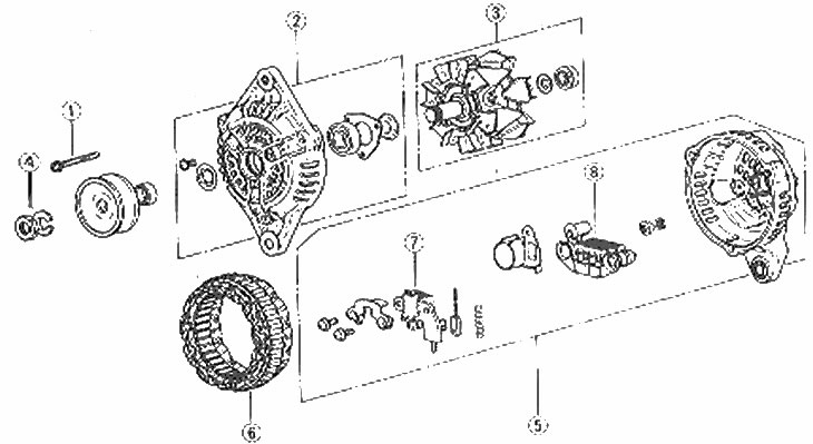
Generator components. In this type the fan is built into the rotor
1. Casing screw; 2. Drive housing, bearing and retainer (valve cracker); 3. Rotor and end bearing of the slip ring; 4. Pulley nut and washer; 5. End of housing contact ring and related components; 6. Stator; 7. Fastening the voltage regulator brush; 8. Rectifier
Note: This procedure will require solder.
1. Remove the generator as described in Chapter 13.
2. Unscrew the three screws that hold the two halves of the generator housing together.
3. Heat the bearing housing to 50° - 60°C, but do not overheat other components.
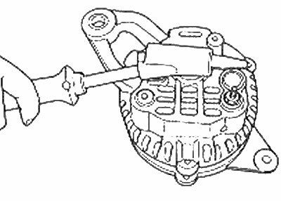
Warm up the ring and bearing housing
4. While the bearing housing is still hot, remove the drive housing and rotor. Be careful not to damage the stator winding. Make sure the slip ring and separator are not lost. Clean the generator rings with a soft cloth soaked in solvent.
5. Loosen the screw securing the voltage regulator brush (photo). Also, loosen the nut and washer of clamp "B.".
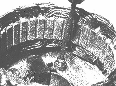
Remove the voltage regulator/brush mounting screw
6. Unsolder the connecting rods from the rectifier to release the voltage regulator brush fastener (photo). Unsolder quickly to avoid damaging the rectifier.
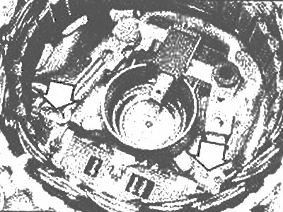
Unsolder the connecting rods (arrow)
7. Remove the voltage regulator brush mounting block. Unsolder the old brushes and solder the new ones (photo). When the new brushes are properly installed, the pole limit line should extend 2-3 mm from the brush holder.
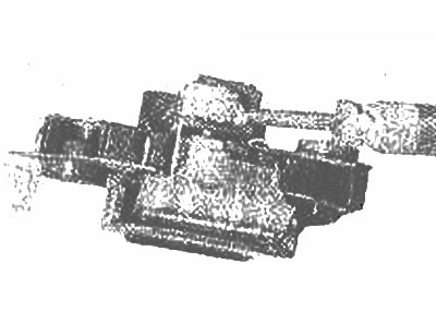
Solder new brushes |
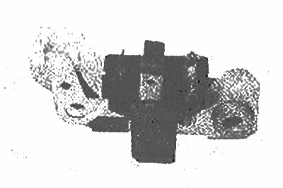
Correctly installed brushes |
8. Install the voltage regulator brush fastener and solder the connecting rods. Install the nut, washer and pin securing the "B" clamp.
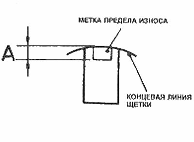
Installing the generator brush
9. Carefully lift the brushes and hold them up. Insert a thin rod or twist drill through the hole in the contact ring of the housing (photo).
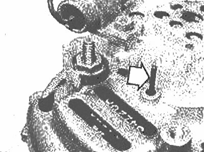
Use a twist drill to hold the brushes in place (marked with arrows)
10. Make sure that the end bearing contact ring retainer is still positioned in the journal bearing oil groove.
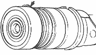
Make sure that the end bearing contact ring retainer (arrow) is in the oil groove (Chapters 14 and 16)
11. Install the three pins that connect the two parts of the body and clamp them.
12. Remove the rod that was used to hold the brushes (photo).
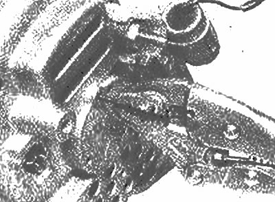
Remove the drill to release the brushes
13. Install the generator (Chapter 13).