
2. Remove the pulley nut and washer (photo).
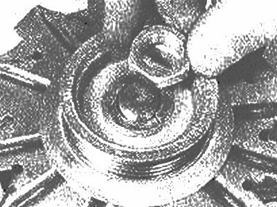
Removing the pulley nut and washer
3. Remove pulley, fan, gasket and concave washer (photo). Note the position of the concave washer.
Remove pulley... | 
... fan... |
... gasket... | 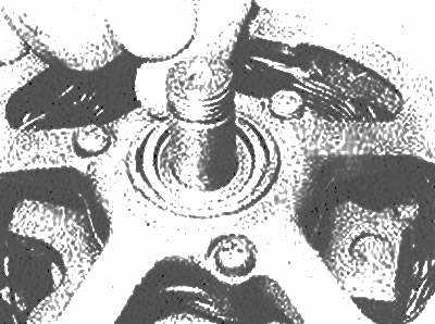
... and an outer concave washer |
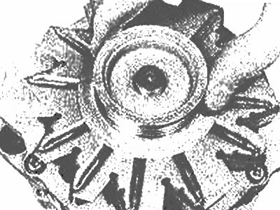
4. Unscrew the three screws securing the case (photo). Fit the slip ring and bearing housing and remove the drive housing and rotor as described in previous Chapter.
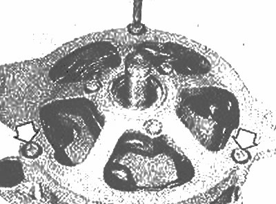
Unscrew the screw securing the case - the other two screws are marked with arrows
5. Knock the rotor off the bearing.
6. Remove the nut and washer from the clamp «IN». From the inside of the case, unscrew the three screws that secure the voltage regulator brush fastener. Take out the stator, etc. from the body.
7. If tests are to be carried out on the stator or rectifier, disconnect them. Note the location of the wires.
8. To replace the brush see chapter 14.
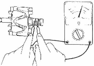
9. Connect a multimeter or 12 volt test light to the stator wires to check for continuity. There must be continuity between any pair. Replace the stator if it fails the test.
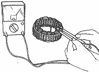
Checking the stator winding for continuity
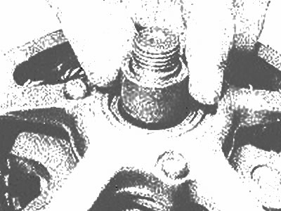
10. Inspect the rotor for damage, paying special attention to the alternator rings (photo). Small deposits can be removed with fine sandpaper, then wipe them with a soft cloth dampened with solvent. If there is serious damage, the rotor must be replaced.
Insulation test between stator windings and lamination | 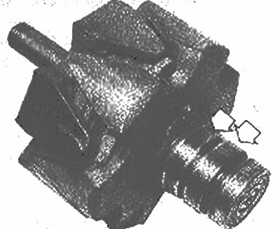
Check generator rings (canceled by arrows) for damage |
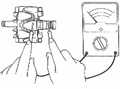
11. Use a multimeter or test light to check continuity between the generator rings. Compare the rotor winding resistance with the data in Specifications. Also check the continuity between each slip ring and the lamination of the rotor. Replace the rotor if it fails these tests.
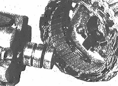
Measuring the resistance of the rotor winding
12. Check rotor bearings. Replace them if they are damaged. Make sure the slip ring end bearing is installed correctly.
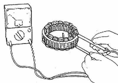
13. Using a multimeter or test light, check the pairs for continuity. If there is discontinuity in the pair, replace the whole stator.
14. Solder the ends of the voltage regulator/brush stator and rectifier. Install the assembly on the body, fix the clamp with screws and a nut «IN».
15. Raise and secure the brushes as described in the previous Chapter. Check that the end bearing slip ring retainer is locked, lubricate the bearing sliding groove, then heat the slip ring end bearing housing and install the rotor (photo).
Rotor installation
16. Place the concave washer on the rotor axle, checking for correct installation (photo). Position the drive end housing over the rotor and push it into place. Install and tighten the three housing screws.
Insulation test between rotor windings and lamination | 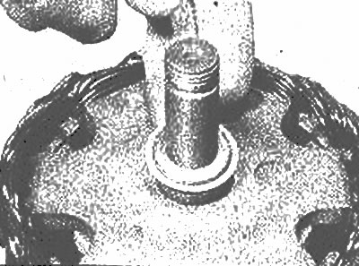
Correct installation of the inner concave washer |
17. Install another concave washer, gasket, fan and pulley. Clamp the pulley and install the washer and nut.
18. Release the brushes, then install the generator (Chapter 13).