
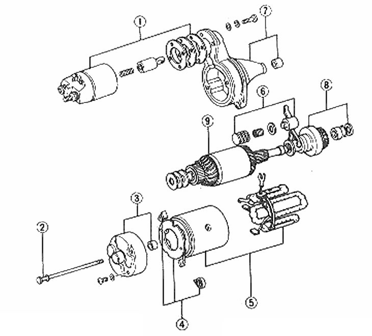
Starter parts
1. Solenoid and gaskets; 2. Coupling bolt; 3. Anchor cover and sleeve; 4. Brush components; 5. Pole shoe and field coils; 6. Control arm components; 7. Drive cover and sleeve; 8. Assembling the clutch gear; 9. Anchor
Removing
1. Remove the starter from the car (Chapter 18) and clear it.
2. Unscrew the nut that secures the connecting strap to the traction relay. Remove the belt.
3. Remove two or three screws that secure the traction relay to the starter housing. Remove the solenoid plug and gaskets, noting their numbers and location. Remove the spring.
4. Disconnect the solenoid plunger from the control lever.
5. Remove all three brushes as described in the previous Chapter. Remove the brush mounting plate.
6. Gently pull the plug off the cover.
7. Disconnect the control lever from the gear clutch.
8. Remove anchor, clutch and gears from starter housing.
9. To remove the gear/clutch assembly from the cover, secure it in a vise. Use a hammer and a piece of pipe to lower the bearing against the gear until the spring ring is free. Remove the spring ring, bearing and gear/clutch.
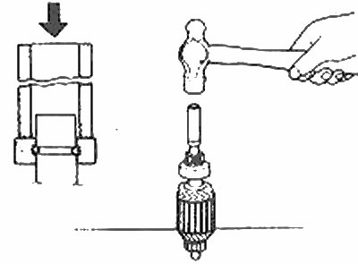
Removing the gear/clutch assembly
Inspection
10. Use a multimeter to check the armature insulation resistance. The resistance between any commutator share and the armature layers must be infinite (open circuit).
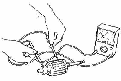
Armature Insulation Resistance Test
11. Inspect the switch for burnout or other damage. Grinding a burned-out layer of metal is sometimes possible, but this is the work of a specialist. Remove carbon and other dirt between the manifold plates with a knife blade or similar tool. The depth of the slots should be as shown in the figure.
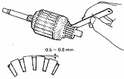
Undercutting the switch
12. Check the insulation resistance between the field winding connector and the stator housing. It must be endless (make sure the field brushes do not touch the stator housing). Check the resistance between the field wires of the brush - it should be negligible.
13. Check the resistance between the brush mounting plate and each volitional (positive) brush holder - it should be infinite. Otherwise, replace the brush mounting plate.
14. Examine brushes and if it is necessary replace them as it is described in the previous Chapter.
15. The armature end brushes can be removed from the casings and replaced if necessary with new ones. Some of these brushes must be lubricated with engine oil before installation.
16. Examine elements of the traction relay on signs of damage and clean corrosion. Function checking will be described later.
Bulkhead
17. Begin assembly by attaching gear/clutch to armature shaft. Place the pinion/clutch on the shaft and secure with a circlip. Install a new circlip into the shaft groove and secure it by bending the circlip locking rim upwards using a pair of double end wrenches.
18. Install the armature in the drive housing. Insert the start lever into the clutch/gears. Install the washer and springs on the pivot pin of the start lever and carefully place the pole shoe in place.
19. Install the brush holder, gaskets, commutator end cap, and tie bolts as described in previous Chapter.
20. Hook the rod of the traction relay switch with the starting lever. Install the spring, pole shoe and shims using the same number of shims as noted when removing. Install and tighten the screws securing the traction relay, but do not attach the drive belt.
Stationary testing
21. For testing, you will need a 12 V battery and some load resistors.
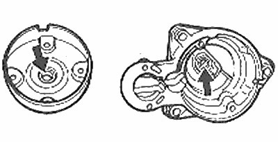
starter caps i bushings (marked with arrows)
22. Test the timing function by connecting the negative battery terminal to the traction relay pole shoe and clamp «M» (big bottom). Connect the positive battery terminal to the clamp «S»: the traction relay should work and the gear will move outward. Do not apply voltage for more than ten seconds.
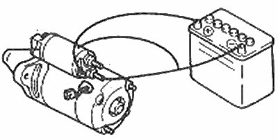
Checking the synchronization function of the traction relay
23. Check function «holding» traction relay, repeating the above test, but disconnecting the terminal «M», leaving the clamp connected «S» pole shoe. The gear should remain in the retracted position.
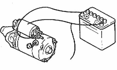
Checking the holding function of the traction relay
24. Test the return function by connecting the positive battery terminal to the clamp «M» and leaving the negative terminal connected to the pole shoe. Pull the gear back by hand and release: it should return immediately.
Checking the return function of the traction relay
25. Replace the traction relay if it fails any of these tests. If the relay is OK, check the drive gear play as follows:
26. Connect the negative terminal to the traction relay pole shoe, and the positive battery terminal to the clamp "S".
27. Gear play can be adjusted by adding or removing shims installed between the pole shoe and icon housing. Adding spacers reduces the gap and vice versa.
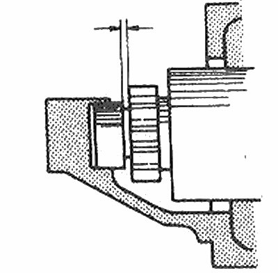
Gear clearance is measured between the arrows
28. If everything is OK, reconnect the cable with the clamp «M» traction relay and fasten with a nut.
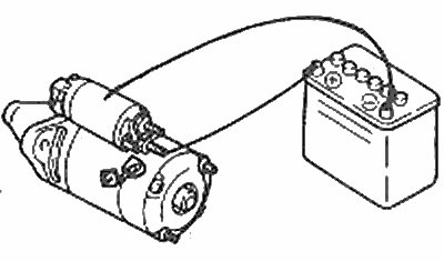
29. If suitable instrumentation is available, measure the starter operating current. Connect the starter as shown in the figure and install it in a vise. At a voltage of 11.5 V, the current should not exceed 60 A and the motor speed should not exceed 6500 rpm. Do not let the engine run at this speed for a long time.
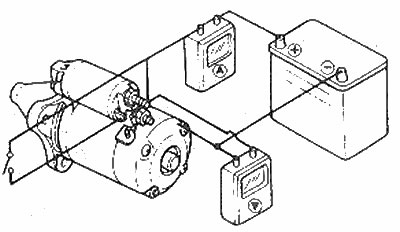
Wiring diagram for measuring starter operating current