Contents: Check on the car ⇓ Test without load ⇓ Checking the retractor clutch ⇓ Checking the return ⇓ Checking the gear clearance (cars…⇓ Checking the starter anchor ⇓ Checking the magnetic starter switch ⇓ Checking the brushes and brush holder ⇓
Check on the car
1. Make sure the battery is fully charged.
2. The starter is normal if it rotates smoothly and without any extraneous noise. If the starter does not work, remove it from the engine and check its technical condition. Check the corresponding electrical wiring, ignition switch and gearbox mode switch (automatic transmission) or starter intermediate switch (manual transmission).
Test without load
1. Make sure the battery is fully charged.
2. Connect the starter, battery and tester as shown in the figure.
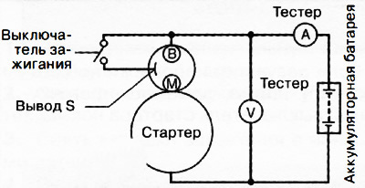
3. Turn on the starter and make sure it rotates smoothly. If the starter does not rotate smoothly, check the technical condition of the starter.
4. Measure the voltage and current while the starter is running. If the measurement results are not correct, replace the starter with a new one.
Note:
Starter voltage without load: 11 V.
Starter current without load:
- cars with i-stop system: no more than 90A
- cars without i-stop system: no more than 95A
(Text taken from an online platform: mazbook)
Checking the retractor clutch
Note: Depending on the state of charge of the battery, the starter pinion may rotate in the extended position. This is due to the current flowing through the pull-in winding rotating the starter, which is not a malfunction.
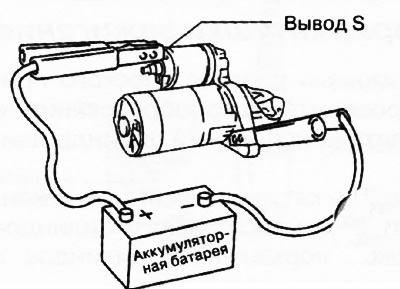
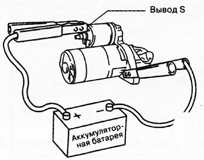
Make sure the starter pinion extends when the positive battery terminal is connected to the S terminal of the starter and the starter housing is grounded. If the starter pinion does not extend, repair or replace the starter.
Checking the return
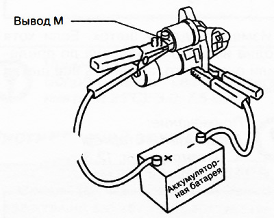
1. Disconnect the wire from the M terminal of the starter.
2. Connect the positive terminal of the battery to terminal M of the starter and connect the starter housing to ground.
3. Pull out the starter pinion with a screwdriver. Make sure that the pinion returns to its original position after being released. If the pinion does not return to its original position, repair or replace the starter.
Checking the gear clearance (cars without i-stop system)
1. Connect the positive pole of the battery to terminal S and connect the starter housing to ground, and extend the starter gear.
Caution: Applying voltage for more than 10 seconds may damage the starter. Do not apply voltage for more than 10 seconds.
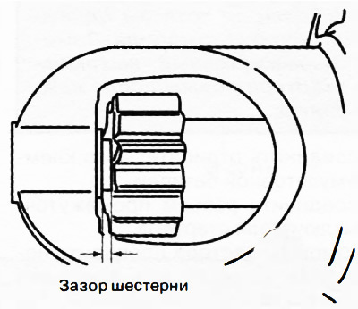
2. Measure the clearance in the extended gear. If the measured value is not within the norm (0.5-2.0 mm), adjust it with a suitable washer (between the front cover of the drive and the magnetic switch).
Checking the starter anchor
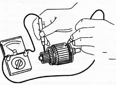
1. Using a tester, check for conductivity between the commutator and the anchor core on each segment. If the circuit is closed, replace the anchor with a new one.
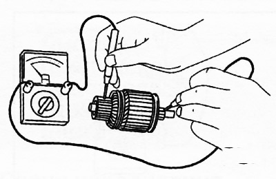
2. Using a tester, make sure there is no conductivity between the commutator and the shaft. If the circuit is closed, replace the anchor with a new one.
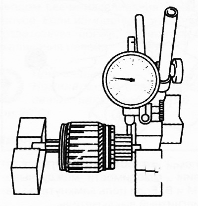
3. Place the starter armature on the V-blocks and measure the runout using a dial indicator. If the measured value is not within the normal range, (no more than 0.1 mm), replace the anchor with a new one.
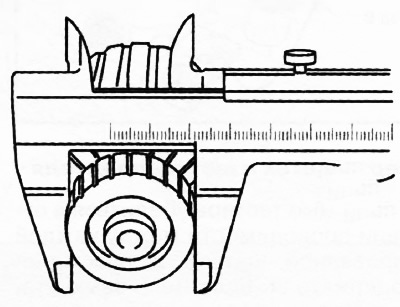
4. Measure the commutator diameter. If the obtained value does not correspond to the maximum permissible value (28.8 mm), replace the anchor with a new one.
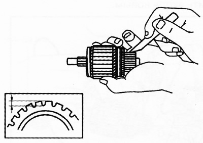
5. Measure the depth of the grooves between the commutator segments. If the measured value is less than the maximum allowable (0.2 mm), trim the grooves to the standard depth (0.5 mm).
Checking the magnetic starter switch
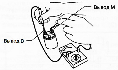
1. Using a tester, check the conductivity between terminals S and M. If the circuit is open, replace the magnetic switch with a new one.
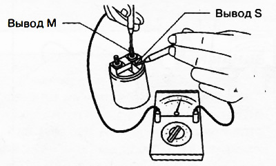
2. Using a tester, check the continuity of the circuit between terminal S and the magnetic switch body. If the circuit is open, replace the magnetic switch with a new one.
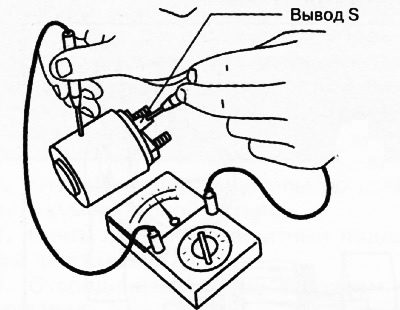
3. Using a tester, make sure there is no conductivity between terminals M and B. If the circuit is closed, replace the magnetic switch.
Checking the brushes and brush holder
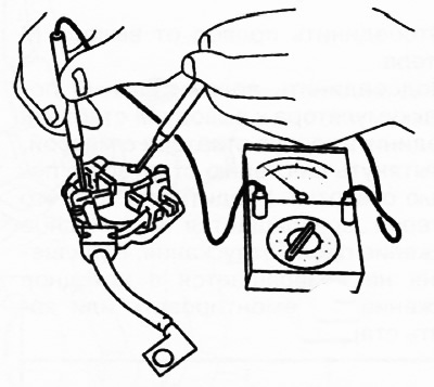
1. Using a tester, check for continuity between each insulated brush and the brush holder plate. If the circuit is closed, replace the brush holder with a new one.
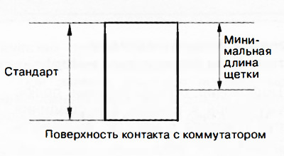
2. Measure the length of the brushes. If at least one of the brushes is worn to the limit or close to it, replace all the brushes with new ones.
Note:
Starter brush length:
- Standard: 12.3 mm.
- Minimum: 5.5 mm.
3. Using a dynamometer, measure the clamping force of the brush springs. If the measured value is less than the minimum (2.75 N), replace the brushes with the brush holder assembly with new ones.