
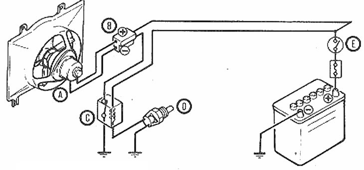
Cooling fan circuit
A - Fan motor; B - Fan connector; C - Relay; D - Thermal switch; E - Ignition switch
Description
1. The system consists of a fan motor, an impeller assembly, a fan relay mounted on the inner panel of the left wing, and a thermal switch screwed into the thermostat housing. The impeller is installed in the fan casing, which is bolted to the radiator.
2. When the coolant in the thermostat housing reaches 97°C, the thermal switch breaks the circuit through the relay, which turns on the fan motor. When the temperature drops below 90°C, the fan motor is switched off.
Operation check and replacement
Fan motor
3. Locate the motor wiring connector and disconnect it with a screwdriver.
4. Using an ammeter, measure the current in the motor circuit as shown in the illustration, and compare the result with the data given in Specifications.
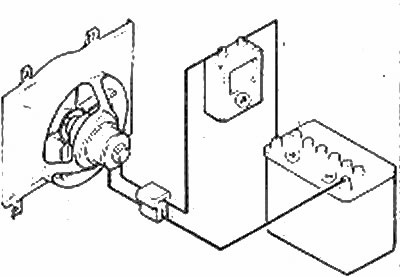
Measure the current
5. If the current from which the fan operates does not match the regulated value, replace the motor (Chapter 6).
Fan relay
6. Disconnect the thermal switch connector and check that the fan starts to rotate when the ignition switch is turned to the "ON". This means the relay is good.
7. If the fan does not rotate, check the contacts and the fuse are good. If the fuse is not blown and the contacts are connected securely, replace the relay. To do this, disconnect the relay connector and remove the fixing screws.
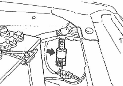
Cooling Fan Relay Location (arrow)
Thermal switch
Note: Do not disconnect the brake switch when the ignition switch is set to "ON" otherwise the fan will turn on automatically.
8. Drain some of the coolant from the cooling system so that its level drops below the thermostat housing.
9. Disconnect the connector and remove the thermal switch.
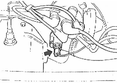
Cooling Fan Thermal Switch Location (arrow)
10. Place the thermal switch in a container of hot water and make sure its contacts are closed at temperatures below 90°C. Heat the water and make sure the switch contacts open before the water boils. If the switch does not work as described, replace it.
11. When installing the circuit breaker, be sure to install the O-ring.
12. Finally, fill the cooling system.