
MazBook.ru
English Русский
Български
Беларускі
Український
Српски
Hrvatski
Română
Polski
Slovenský
Magyar
• Bookmark • Sitemap • Contacts •   
Cars Opel Cars Ford Cars Volkswagen Cars Audi Cars Kia Cars Renault Cars Peugeot


Familia Capella Mazda3 Mazda6 CX-? Others Articles
Mazda 121 (3) (1996-2003) Mazda BT-50 (1) (2006-2011)

Pressure modulator and ABS control unit (Mazda BT-50 (1))

  • Home
  • Mazda
  • BT-50 J97M (2006-2011)
  • Chassis
  • Brake system
  • Pressure modulator and ABS control unit
0

Removal and installation


Caution: Do not allow the pressure modulator to fall, as this will damage the internal components.


Remove the parts in the order they are numbered in the assembly drawing "Removing and installing the pressure modulator and the ABS control unit".

Note: Installation is carried out in the reverse order of removal.


Notes on removal

1. Lift the retainer and disconnect the connector from the pressure modulator.
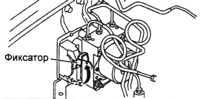
1. Lift the retainer and disconnect the connector from the pressure modulator.


2. When removing the pressure modulator, protect the connector from brake fluid.

3. Apply identification marks to the brake lines and pressure modulator.
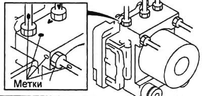
3. Apply identification marks to the brake lines and pressure modulator.


4. Loosen the nuts and disconnect the tubes from the pressure modulator.
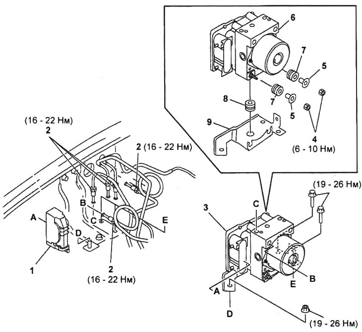
Removal and installation of the pressure modulator and the ABS control unit.

Removal and installation of the pressure modulator and the ABS control unit.
1 - connector,
2 - brake pipe,
3 - pressure modulator and ABS control unit assembled with bracket,
4 - nut,
5 - washer,
6 - pressure modulator and ABS control unit,
7 - bushing (from the pressure modulator side),
8 - bushing (from the bracket side),
9 - bracket.


Installation Notes


1. Connect the brake pipes to the pressure modulator in accordance with the marks made during disassembly.

Original material on the website [www.mazbook.ru]
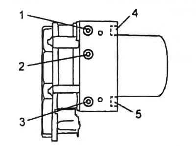
1 - front left wheel contour tube,

1 - front left wheel contour tube,
2 - front right wheel contour tube,
3 - rear wheel contour tube,
4 - main brake cylinder pipe (secondary circuit),
5 - main brake cylinder pipe (primary circuit).


2. Tighten the brake pipe mounting nuts to the specified tightening torque.
  • Tightening torque - 16-22 Nm

3. Connect the connector to the pressure modulator and lower the lock. Make sure the connector is securely connected.
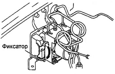
3. Connect the connector to the pressure modulator and lower the lock. Make sure the connector is…
This article is available at: russian, bulgarian, belarusian, ukrainian, serbian, croatian, romanian, polish, slovak, hungarian
This text was checked by: Vladimir Bazhenov
Share with friends on social networks:

Previous
Mazda BT-50 (1) » Brake system
Next

Reading and erasing fault codes
ABS System Diagnostics — System Description
Removal and installation parking brake cables
Checking the parking brake sensor
Parking brake lever
Front Wheel Speed Sensors — Checking
Front Wheel Speed Sensors — Removal and Installation
Rear Wheel Speed Sensors — Check
Rear Wheel Speed Sensors — Removal and Installation
Slowdown sensor
More articles on repairing other Mazda models
Heater control unit Mazda Familia 6 (1989-1994)
Control unit of the RVT system (since 1984) Mazda Capella 3 and 4 (1982-1992)
DSC HU/CM Dynamic Stability Control Unit Mazda3 BK (2003-2009)
DSC HU/CM Dynamic Stability Control Unit Mazda6 GG (2002-2008)
Configuration of the electronic engine control unit Mazda CX-5KE (2012-2017)
Link in different formats to this article
Comments and feedback from visitors
No comments yet


How much will 32 + 20 ?


Mazda BT-50 (1) (2006-2011) 
  • General information
  • Introduction to guide
  • User manual
  • Maintenance
  • Power unit
  • Engine repair (diesel)
  • Cooling and lubrication system
  • Fuel injection system
  • Intake and exhaust system
  • Engine electrical equipment
  • Transmission
  • Clutch
  • Mechanical gearbox
  • All-wheel drive system
  • Transfer case and gearboxes
  • Chassis
  • Front suspension
  • Rear suspension
  • Steering
  • Brake system
  • Body
  • Exterior (external elements)
  • Interior (internal elements)
  • Heating and air conditioning
  • Security system SRS
  • Electrical equipment
  • Equipment and devices
  • Electrical circuits
Mazda 121 (3) (1996-2003) 
  • General information
  • User manual
  • Maintenance
  • Power unit
  • Petrol engine 1.3 l
  • Petrol engine 1.25/1.4 l
  • Diesel engine
  • Lubrication system
  • Cooling system
  • Ignition system
  • Supply system
  • Fuel injection (gasoline)
  • Fuel injection (diesel)
  • Exhaust system
  • Transmission
  • Clutch
  • Car gearbox
  • Chassis
  • Front suspension
  • Rear suspension
  • Steering
  • Brake system
  • Wheels and tires
  • Body
  • Exterior (external elements)
  • Interior (internal elements)
  • Doors, windows and locks
  • Heating system
  • Electrical equipment
  • Troubleshooting
  • Equipment and devices
  • Lighting system
  • Power devices
  • Electrical circuits
MazBook.ru © 2018–2026 · Mobile version · Articles and news · Sitemap: EN BG BY UA RS HR RO PL SK HU · Feedback · Site search · Add to bookmarks Familia 5 (BF) · Familia 6 (BG) · Capella 3 (GC) · Capella 3 and 4 (GC) · Capella 4 (GD) · Capella 5 (GE) · Capella 6 (GF) · Mazda3 BK · Mazda6 GG · CX-5KE · Mazda 121 (3) · Mazda BT-50 (1) ·
By continuing to use the site, you agree to the use of cookies 🔐