
2. Remove the parts in the order they are numbered on the assembly drawing "Parking brake lever".
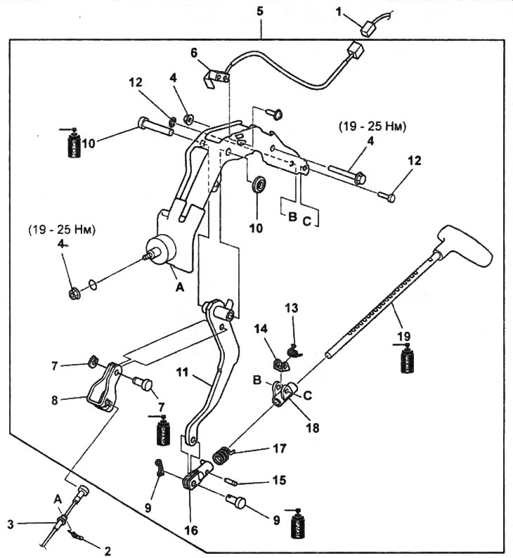
Parking brake lever.
1 - parking brake sensor connector,
2 - latch,
3 - front parking brake cable,
4 - bolt and nut,
5 - parking brake lever assembly,
6 - parking brake activation sensor,
7 - retaining ring and pin,
8 - cable fork,
9 - cotter pin and pin,
10 - latch and lever axis,
11 - lever,
12 - retaining ring and pin,
13 - spring,
14 - doggy,
15 - stopper,
16 - fork,
17 - spring,
18 - guide,
19 - parking brake lever.
Note:
- Installation is made in an order, the return to removal.
- After installation, check and, if necessary, adjust the stroke of the parking brake lever.