
Attention: carrying out further repair operations without first removing the wheel speed sensor (ABS) may damage the sensor wiring. To prevent damage to the sensor or its wiring, remove the wheel speed sensor and secure it out of the way before making major repairs.
Remove parts in the order they are numbered on the assembly drawing "Removal and installation of a support".
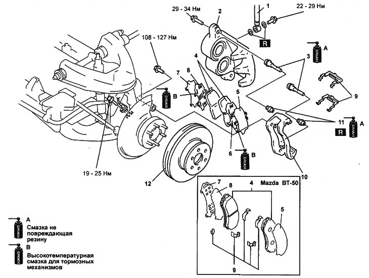
Removal and installation of a support.
1 - brake hose,
2 - support,
3 - guide pin,
4 - brake pads,
5 - outer gasket,
6 - external anti-creak gasket,
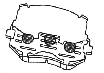
7 - inner lining,
8 - internal anti-creak gasket,
9 - shoe guide,
10 - caliper bracket,
11 - anther,
12 - brake disc.
Note:
- Installation is made in an order, the return to removal.
- After installation, press the brake pedal several times and, turning the wheels by hand, make sure that the track turns easily and smoothly.
Withdrawal Notes
1. Remove the brake shoe guides.
Raise the end of the guide in the direction (1). Then rotate the guide in the fix (2) and take it off.
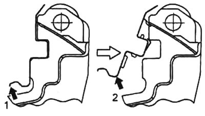
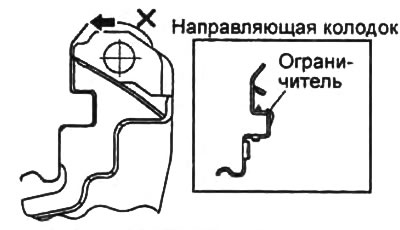
Note: Do not remove the brake pad guides using the method shown in the illustration. This will damage the stopper and make the guide unusable.
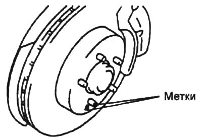
7. Mark the wheel stud and brake disc. Remove the brake disc.
Installation Notes
1. Before installing the brake disc, clean the contact surfaces of the hub and the brake disc from dirt and rust.
2. Install gaskets.
A) Install anti-squeak pads on the brake pads and apply high temperature brake grease to the pads in the areas shown in the illustration.
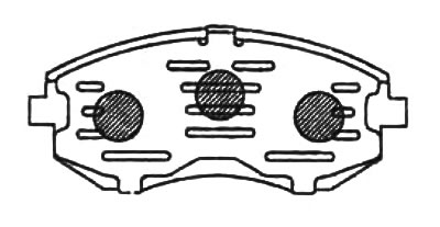
b) Install the gasket but the brake pad.
Attention: do not allow lubricant to get on the working surfaces of the brake pad.
3. Install the brake pads.
A) Using the special tool, fully sink the pistons into the cylinders.
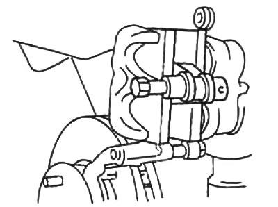
b) Install the brake pads.