
Removal and installation
Remove the parts in the order they are numbered in the assembly drawing below.
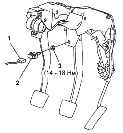
1 - brake light switch connector,
2 - brake light switch,
3 - nut.
Note:
- Installation is made in an order, the return to removal.
- After installation, check and, if necessary, adjust the height, free play and reserve of the brake pedal (see subsection "Check and adjustment).
Examination
1. Disconnect a wire from the negative plug of the storage battery.
2. Remove the bottom trim on the driver's side.
3. Disconnect the brake light switch connector.
4. Check for continuity between the leads "A" And "IN" brake light switch when the brake pedal is depressed and no conduction when the pedal is released.
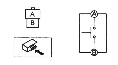
If necessary, replace the brake light switch.