
Examination
Note: Before checking, make sure that the fuel tank is full, all systems are filled with the nominal amount of fluid and the spare tire, tool and jack are in place.
1. Park the vehicle on a level, level surface.
2. Check tire wear and tire pressure. Replace tires and/or adjust tire pressure if necessary.
3. Connect pressure gauges to the front wheel caliper fittings and rear wheel slave cylinder. Bleed the assembled system with a valve "A".
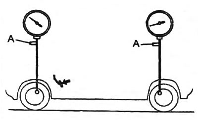
4. Slowly depress the brake pedal until the pressure in the front wheel circuit reaches 4900 kPa.
5. Measure the pressure in the rear wheel circuit.
Pressure:
- models without ABS - 2250 - 2850 kPa
- models with ABS - 2650 - 3450 kPa
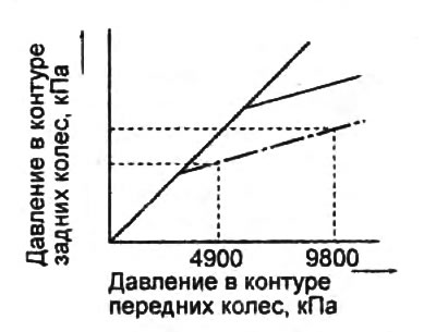
6. Press the brake pedal and increase the pressure in the front wheel circuit to 9800 bar.
7. Measure the pressure in the rear wheel circuit.
Pressure:
- models without ABS - 3130 - 3930 kPa
- models with ABS - 4700 - 5900 kPa
8. If the pressure in the rear wheel circuit is not correct, adjust.
Adjustment
Note: Before adjusting, make sure the fuel tank is completely filled, all systems are filled with the nominal amount of fluid and the spare tire, tool and jack are in their original places.
1. Loosen the nuts shown in the figure and move the adjusting lever to adjust the length of the spring.
- Nominal length - 175.5-182.5 mm
Note: when the spring length is changed by 5 mm, the pressure changes by the amount indicated in the tables below.
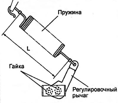 | 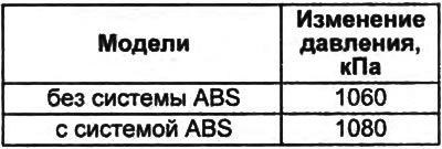 |
Note: when the length of the spring is reduced, the pressure decreases, when the length is increased, it increases.
2. Tighten the nut.
- Tightening torque - 19 - 59 Nm
3. After the adjustment, repeat the verification procedure.
If necessary, replace the load-dependent brake force distribution valve.
Removal and installation
Attention:
- Do not disassemble the load-dependent brake force distribution valve.
- Don't turn the nut "A".
Remove the parts in the order mx numbering in the assembly drawing "Removal and installation of the valve for redistribution of brake forces depending on the load".
Note:
- Installation is made in an order, the return to removal.
- After installation, follow the spring length adjustment procedure.
Installation note
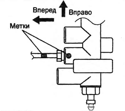
When connecting the brake pipes to the brake force redistribution valve, align the marks on the pipes and the valve.
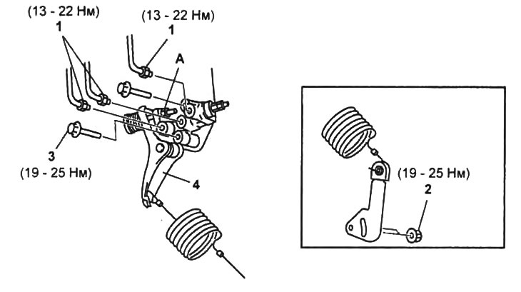
Removal and installation of the valve of redistribution of brake forces depending on the load.
1 - brake pipe,
2 - nut,
3 - bolt,
4 - valve for redistribution of braking forces depending on the load.