


Attention.
When configuring, it is necessary to read the calibration data of the coupler from the four-wheel drive control unit before replacing it. Connect the M-MDS to the vehicle and perform vehicle identification before removing the AWD control unit. Coupling calibration data is temporarily stored in the M-MDS.
If the configuration is not carried out after replacing the AWD control unit, the following complications may occur due to the lack of recording of the coupling calibration data in the AWD control unit:
- The system will not work normally.
- There may be performance issues with the 4WD clutch.
Note:
- The AWD control unit saves the coupling calibration data before replacement.
- If the calibration data from the four-wheel drive control unit, saved before it was replaced, cannot be read, read the calibration data of the coupler.
1. When replacing the four-wheel drive control unit, perform the configuration.
2. Disconnect the negative battery terminal.
3. Remove the front door sill trim.
4. To remove forward lateral facing of salon.
5. Disconnect the connector and unscrew the bolt securing the all-wheel drive control unit.
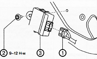
1. Connector
6. Move the four-wheel drive control unit towards the connector and remove.
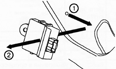
7. Installation is made in an order, the return to removal.
Note: If the configuration will not be done by reading/writing the coupler calibration data, perform the calibration data reading as described below.
All-wheel drive control unit configuration
Attention. When configuring, it is necessary to read the calibration data of the coupler from the four-wheel drive control unit before replacing it. Connect the M-MDS to the vehicle and perform vehicle identification before removing the AWD control unit. Coupling calibration data is temporarily stored in the M-MDS.
1. Connect the M-MDS device to the DLC-2 diagnostic socket.
2. After vehicle identification, select the following parameter in M-MDS:
- "Module Programming" (programming module)
3. Then select options from the OSD menu:
- "Programmable Module installation" (installation of a programmable module)
- "4x4" (four-wheel drive)
4. Complete the configuration according to the instructions on the screen.
Attention. When performing a configuration, the CAN connection between the four-wheel drive control unit and other control units connected by the CAN bus may be temporarily interrupted with the appearance of the corresponding fault code. After completing the configuration, it is necessary to check for fault codes in the control units connected to the CAN bus, and, if found, delete these codes.
5. Check for fault codes in control units connected to the CAN bus. If fault codes are found, delete them. After deleting the codes, complete the procedure, since the configuration is over. If trouble codes do not clear, troubleshoot for the problem that is found.
Reading calibration data
1. Connect the M-MDS device to the DLC-2 diagnostic socket.
2. After vehicle identification, select the following parameter in M-MDS:
- "Chassis" (chassis)
3. Then select options from the OSD menu:
- "4WD/AWD" (permanent/plug-in all-wheel drive)
- "Coupling Calibration Data writing" (read clutch calibration data)
4. Read the coupler calibration data as instructed on the screen.
5. Check for fault codes in control units connected to the CAN bus. If fault codes are found, delete them. After deleting the codes, complete the procedure, since the configuration is over. If trouble codes do not clear, troubleshoot for the problem that is found.